Surveying I and Workshop Technology I (Mechanical) — June/July 2025
KNEC Diploma in Civil Engineering — Module I. Paper code: 2707/104 (shared paper: 2705/104, 2709/104 and 2710/104). Time: 3 hours.
Attempt each question before reading the answer. These are independent revision answers, not official KNEC marking schemes. All eight printed questions, including the optional questions, are answered for revision.
The paper instructs candidates to answer five questions, choosing at least two from Section A and at least two from Section B, plus one other question from either section.
Question 1
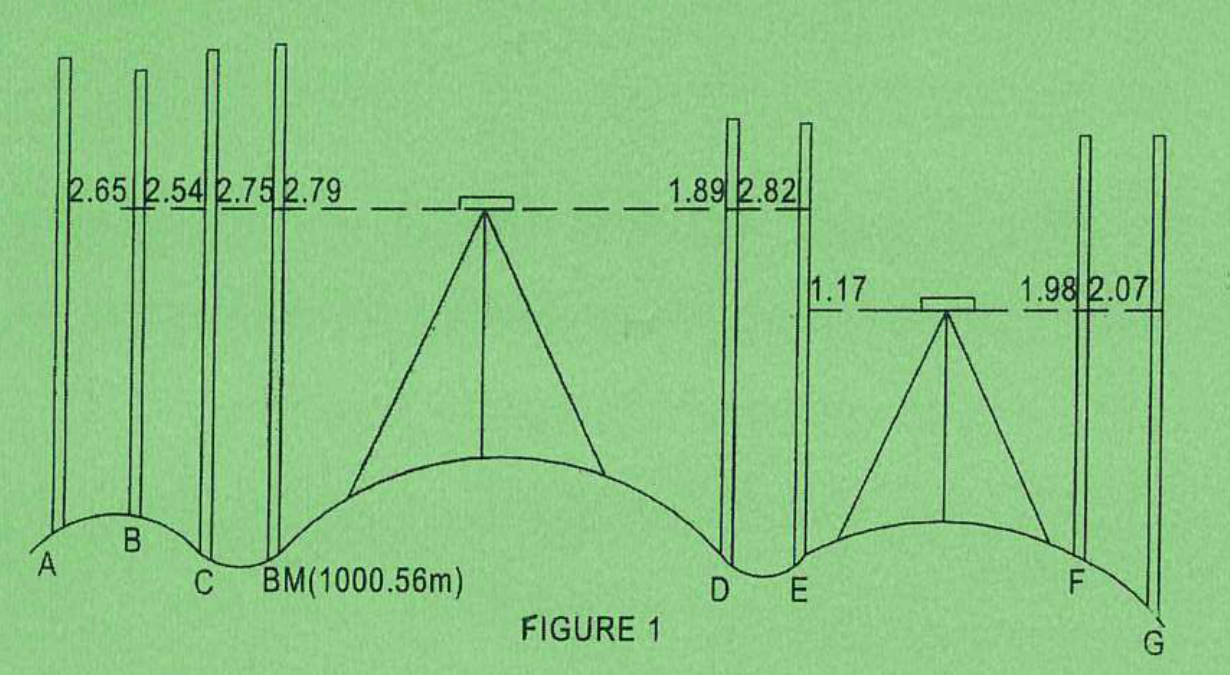
Figure 1 shows staff readings taken along a proposed road centre line. Book the readings in a standard format and reduce them by "Rise and Fall" method. Apply arithmetic checks.
(20 marks)
Answer
The known bench mark is 1000.56 m. E is the change point: its foresight is 2.82 m from the first setup and its backsight is 1.17 m from the second setup.
| Initial calculation | Working | Result (m) |
|---|---|---|
| First setup HC | 1000.56 + 2.79 | 1003.35 |
| Starting RL at A | 1003.35 − 2.65 | 1000.70 |
| Point | BS (m) | IS (m) | FS (m) | Rise (m) | Fall (m) | RL (m) | Remarks |
|---|---|---|---|---|---|---|---|
| A | 2.65 | — | — | — | — | 1000.70 | Start |
| B | — | 2.54 | — | .11 | — | 1000.81 | |
| C | — | 2.75 | — | — | .21 | 1000.60 | |
| BM | — | 2.79 | — | — | .04 | 1000.56 | Known level |
| D | — | 1.89 | — | .90 | — | 1001.46 | |
| E | 1.17 | — | 2.82 | — | .93 | 1000.53 | CP |
| F | — | 1.98 | — | — | .81 | 999.72 | |
| G | — | — | 2.07 | — | .09 | 999.63 | Last |
| Arithmetic check | Calculation | Result (m) |
|---|---|---|
| ΣBS − ΣFS | (2.65 + 1.17) − (2.82 + 2.07) = 3.82 − 4.89 | −1.07 |
| Σrise − Σfall | (0.11 + 0.90) − (0.21 + 0.04 + 0.93 + 0.81 + 0.09) | −1.07 |
| Last RL − first RL | 999.63 − 1000.70 | −1.07: all three agree |
Question 2(a)
Table 1 shows readings from a level book. Determine the reduced level of the points P1, P2, P3, P4, P5, P6, P7 using the "Height of collimation" method. Apply necessary arithmetic checks.
| BS | IS | FS | Remarks |
|---|---|---|---|
| 1.963 | — | — | P1 |
| — | 2.856 | — | P2 |
| — | 3.252 | — | P3 |
| — | 3.452 | — | P4 |
| 2.185 | — | 3.781 | P5 |
| — | 4.123 | — | P6 |
| — | 3.189 | — | BM (860.56 m) |
| — | — | 2.463 | P7 |
(12 marks)
Answer
| Step | Calculation | Result (m) |
|---|---|---|
| Second HC from bench mark | 860.560 + 3.189 | 863.749 |
| Change point P5 | 863.749 − 2.185 | 861.564 |
| First HC | 861.564 + 3.781 | 865.345 |
| Reduce all points | RL = appropriate HC − staff reading | See completed book |
| Point | BS (m) | IS (m) | FS (m) | HC (m) | RL (m) | Remarks |
|---|---|---|---|---|---|---|
| P1 | 1.963 | — | — | 865.345 | 863.382 | Start |
| P2 | — | 2.856 | — | — | 862.489 | |
| P3 | — | 3.252 | — | — | 862.093 | |
| P4 | — | 3.452 | — | — | 861.893 | |
| P5 | 2.185 | — | 3.781 | 863.749 | 861.564 | CP: FS then BS |
| P6 | — | 4.123 | — | — | 859.626 | |
| BM | — | 3.189 | — | — | 860.560 | Known RL |
| P7 | — | — | 2.463 | — | 861.286 | Last |
| Arithmetic check | Calculation | Result (m) |
|---|---|---|
| ΣBS − ΣFS | (1.963 + 2.185) − (3.781 + 2.463) = 4.148 − 6.244 | −2.096 |
| Last RL − first RL | 861.286 − 863.382 | −2.096: agrees |
Question 2(b)
Plot a profile if the points were picked at an interval of 20 M using scales of: 1:1000 horizontal and 1:100 vertical.
(8 marks)
Answer
Take the eight ground points in their recorded order, including the bench mark, at successive 20 m intervals. The two readings at change point P5 occupy one position.
| Point | Chainage (m) | RL (m) |
|---|---|---|
| P1 | 0 | 863.382 |
| P2 | 20 | 862.489 |
| P3 | 40 | 862.093 |
| P4 | 60 | 861.893 |
| P5 | 80 | 861.564 |
| P6 | 100 | 859.626 |
| BM | 120 | 860.560 |
| P7 | 140 | 861.286 |
| Plotting step | Calculation | Result |
|---|---|---|
| Horizontal interval on paper | 20 m ÷ 1000 | 20 mm |
| Vertical interval on paper | 1 m ÷ 100 | 10 mm |
| Full horizontal plotted length | 140 m ÷ 1000 | 140 mm |
| Vertical exaggeration | 1000 ÷ 100 | 10 |
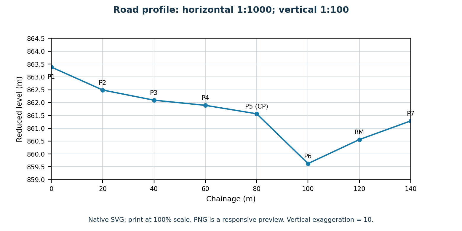
Use a convenient vertical datum below the minimum level, such as RL 859 m. Label the scales, chainages, points, reduced levels and datum.
Question 3(a)
Define each of the following terms in levelling: (i) foresight; (ii) change point; (iii) reduced level; (iv) horizontal surface.
(6 marks)
Answer
| Term | Definition |
|---|---|
| Foresight | The last staff reading from an instrument setup, normally on a change point or the final point, before the level is moved. |
| Change point | A firm point on which a foresight is taken before moving the instrument and a backsight after moving it, to transfer the height reference. |
| Reduced level | The elevation of a point above or below an adopted datum. |
| Horizontal surface | A plane tangent to the level surface at the point considered, perpendicular to the local direction of gravity. |
Question 3(b)
Table 2 shows staff readings obtained during levelling. (i) Rule out a level field book page and enter the readings. (ii) Reduce the levels by the height of collimation method, if the last reading was taken on a benchmark of reduced level 2053.628 m above mean sea level. (iii) Carry out the arithmetic checks.
| BS | IS | FS |
|---|---|---|
| 1.982 | — | — |
| — | 2.157 | — |
| — | 2.345 | — |
| −1.352 | — | −2.146 |
| 2.568 | — | 2.234 |
| — | — | 2.982 |
(14 marks)
Answer
The negative readings are retained exactly. They represent inverted-staff readings on an overhead point; use their algebraic signs in HC = RL + BS and RL = HC − reading.
| Working backwards from the known final BM | Calculation | Result (m) |
|---|---|---|
| Third HC | 2053.628 + 2.982 | 2056.610 |
| RL at CP2 | 2056.610 − 2.568 | 2054.042 |
| Second HC | 2054.042 + 2.234 | 2056.276 |
| RL at CP1 | 2056.276 − (−1.352) | 2057.628 |
| First HC | 2057.628 + (−2.146) | 2055.482 |
| Point | BS (m) | IS (m) | FS (m) | HC (m) | RL (m) | Remarks |
|---|---|---|---|---|---|---|
| 1 | 1.982 | — | — | 2055.482 | 2053.500 | Start |
| 2 | — | 2.157 | — | — | 2053.325 | |
| 3 | — | 2.345 | — | — | 2053.137 | |
| 4 | −1.352 | — | −2.146 | 2056.276 | 2057.628 | CP1: inverted staff |
| 5 | 2.568 | — | 2.234 | 2056.610 | 2054.042 | CP2 |
| 6 | — | — | 2.982 | — | 2053.628 | Final BM: given |
| Arithmetic check | Calculation | Result (m) |
|---|---|---|
| ΣBS | 1.982 − 1.352 + 2.568 | 3.198 |
| ΣFS | −2.146 + 2.234 + 2.982 | 3.070 |
| ΣBS − ΣFS | 3.198 − 3.070 | 0.128 |
| Last RL − first RL | 2053.628 − 2053.500 | 0.128: agrees |
Question 4(a)
State the two differences between 'plane surveying' and 'geodetic surveying'.
(4 marks)
Answer
| Basis | Plane surveying | Geodetic surveying |
|---|---|---|
| Earth curvature | Neglected over the area surveyed; the surface is treated as a plane. | Allowed for using a curved Earth model. |
| Extent and geometry | Suited to relatively small areas; ordinary plane geometry is used. | Suited to extensive surveys and control networks; curved-surface geometry is used. |
Question 4(b)
Outline the field procedure for the 'grid method' of contouring.
(6 marks)
Answer
- Reconnoitre the site, choose a suitable grid spacing and establish control and a bench mark.
- Set out and mark the grid intersections and record their horizontal positions.
- Set up the level, take a backsight on the bench mark and calculate HC.
- Read the staff at each grid intersection and at important breaks of slope between intersections.
- Reduce all readings to RLs and close or check the levelling.
- Plot the grid and spot levels, interpolate the required contour crossings between measured points and draw smooth contour lines.
Question 4(c)
With the aid of a labelled sketch, outline the procedure of ranging a hill between two terminal points.
(6 marks)
Answer
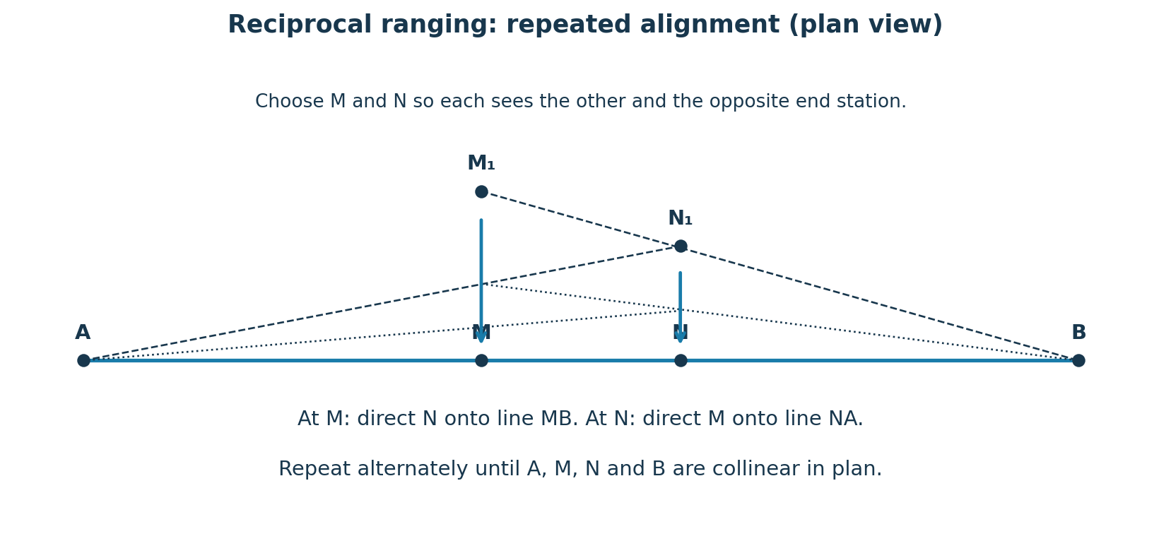
- Place two ranging rods at approximate intermediate positions M and N near the crest. Choose positions so M sees N and B, while N sees M and A.
- From M, direct the assistant at N sideways until N lies on line MB.
- From the corrected N position, direct M sideways until M lies on line NA.
- Repeat these alternate adjustments. The required corrections become smaller until neither observer needs another correction.
- The final rods M and N lie on the straight survey line AB in plan. Mark the stations and measure the line in suitable sections.
Question 4(d)
State the two differences between a change point and a bench mark.
(4 marks)
Answer
| Basis | Change point | Bench mark |
|---|---|---|
| Purpose | Transfers level from one instrument setup to the next. | Provides an established elevation reference relative to a datum. |
| Status and readings | Often a temporary firm point; receives a foresight and then a backsight during the survey. | Normally a stable marked reference with a known RL; may be used at the start, end or as a check. |
A suitable bench mark can also serve as a change point; the terms describe different functions.
Question 5(a)
Explain five roles of employees in health and safety Act.
(10 marks)
Answer
- Take reasonable care of their own health and safety and that of other people affected by their work.
- Cooperate with the employer in carrying out health and safety duties.
- Wear and use the protective clothing and equipment provided for the work.
- Follow the health and safety procedures and instructions given by the employer.
- Report hazards, defective equipment, accidents and injuries promptly to the supervisor or employer so corrective action can be taken.
These points summarise employee duties under section 13 of Kenya’s Occupational Safety and Health Act, 2007.
Question 5(b)
Differentiate between 'water' and 'foam' fire extinguishers.
(4 marks)
Answer
| Basis | Water | Foam |
|---|---|---|
| Main action | Absorbs heat and cools the burning material. | Forms a blanket over the fuel to suppress vapour and separate the flame from air; its water content also cools. |
| Typical suitability | Ordinary combustible solids such as wood, paper and cloth. | Suitable ordinary solids and flammable-liquid surface fires, according to the marked rating. |
Do not use an ordinary water extinguisher on a flammable-liquid spill. Do not assume water or foam is suitable for energised electrical equipment: follow the specific extinguisher rating and site instructions.
Question 5(c)
Explain three holding tools used in a workshop.
(6 marks)
Answer
| Tool | Explanation and use |
|---|---|
| Bench vice | A vice bolted to a bench, with fixed and moving jaws; holds work firmly for filing, sawing or other bench operations. |
| Hand vice | A small portable vice with screw-operated jaws; holds small or thin work that is awkward or unsafe to grip with the fingers. |
| G-clamp / C-clamp | A rigid frame with an adjustable screw pad; clamps a workpiece to a bench or holds components together. |
Question 6(a)
Explain five types of hammers used for striking.
(10 marks)
Answer
| Hammer | Use |
|---|---|
| Ball-peen hammer | Its flat face delivers blows and its rounded peen shapes metal or rivet heads. |
| Cross-peen hammer | The narrow peen is across the handle; used to draw out or shape metal in controlled blows. |
| Straight-peen hammer | The narrow peen is parallel to the handle; used to draw and shape metal where that orientation is useful. |
| Sledgehammer | A heavy hammer, often used with both hands, for heavy driving and forging work. |
| Soft-faced hammer | Faces of materials such as rubber, plastic or copper apply blows while reducing damage to finished components. |
Question 6(b)
State four safety measures observed when using a hacksaw.
(4 marks)
Answer
- Fit a sound blade of suitable tooth pitch in the correct cutting direction and tension it correctly.
- Clamp the work securely, close to the cut, so it cannot slip or vibrate excessively.
- Wear eye protection and keep hands and fingers clear of the blade path.
- Use controlled strokes and suitable pressure; do not twist or force the blade.
Question 6(c)
Outline four safety precautions observed while working on a lathe machine.
(6 marks)
Answer
- Secure the work in the chuck or between centres and clamp the cutting tool at the correct height with minimum overhang.
- Remove the chuck key immediately after use and before starting the spindle.
- Wear eye protection, tie back long hair and secure loose clothing; keep gloves and hands away from rotating work.
- Stop the spindle before measuring, adjusting or clearing the work area. Keep guards in position and remove swarf with a suitable brush or hook after stopping; never use bare hands.
Question 7(a)
Describe each of the following parts of a milling machine: (i) column; (ii) knee; (iii) spindle.
(9 marks)
Answer
| Part | Description and function |
|---|---|
| Column | The main upright body fixed to the base. It supports other machine parts and commonly houses drive mechanisms and guideways. |
| Knee | The vertically adjustable casting carried on the column guideways. It supports the saddle and table and changes their height relative to the cutter. |
| Spindle | The rotating shaft that holds or drives the cutting tool or arbor, transmitting power and maintaining the cutter’s alignment. |
Question 7(b)
State four differences between 'two stroke' and 'four stroke' engines.
(8 marks)
Answer
| Basis | Two-stroke engine | Four-stroke engine |
|---|---|---|
| Strokes in one cycle | Two piston strokes. | Four piston strokes. |
| Crankshaft revolutions in one cycle | One revolution. | Two revolutions. |
| Power-stroke frequency per cylinder | One power stroke each revolution. | One power stroke every two revolutions. |
| Gas exchange in common small-engine designs | Ports and scavenging combine gas-exchange processes near the end of the stroke. | Inlet and exhaust valves operate with separate intake and exhaust strokes. |
The gas-exchange comparison describes common designs. Some large two-stroke engines also use exhaust valves.
Question 7(c)
Describe compression as an operation of a 'four stroke' engine.
(3 marks)
Answer
The piston moves from BDC to TDC with both inlet and exhaust valves closed. The trapped charge is compressed into a smaller volume, increasing its pressure and temperature. Near the end of compression a petrol engine uses a spark to initiate combustion; a diesel engine injects fuel into the hot compressed air.
Question 8(a)
State five factors considered when choosing a water pump.
(5 marks)
Answer
- Required flow rate or discharge.
- Total dynamic head, including suction lift, delivery height and pipe friction.
- Nature of the water, including sediment, corrosiveness and temperature.
- Availability, suitability and operating cost of the power source.
- Purchase cost, efficiency, maintenance needs and availability of service and spare parts.
Question 8(b)
Sketch and label a reciprocating pump.
(7 marks)
Answer
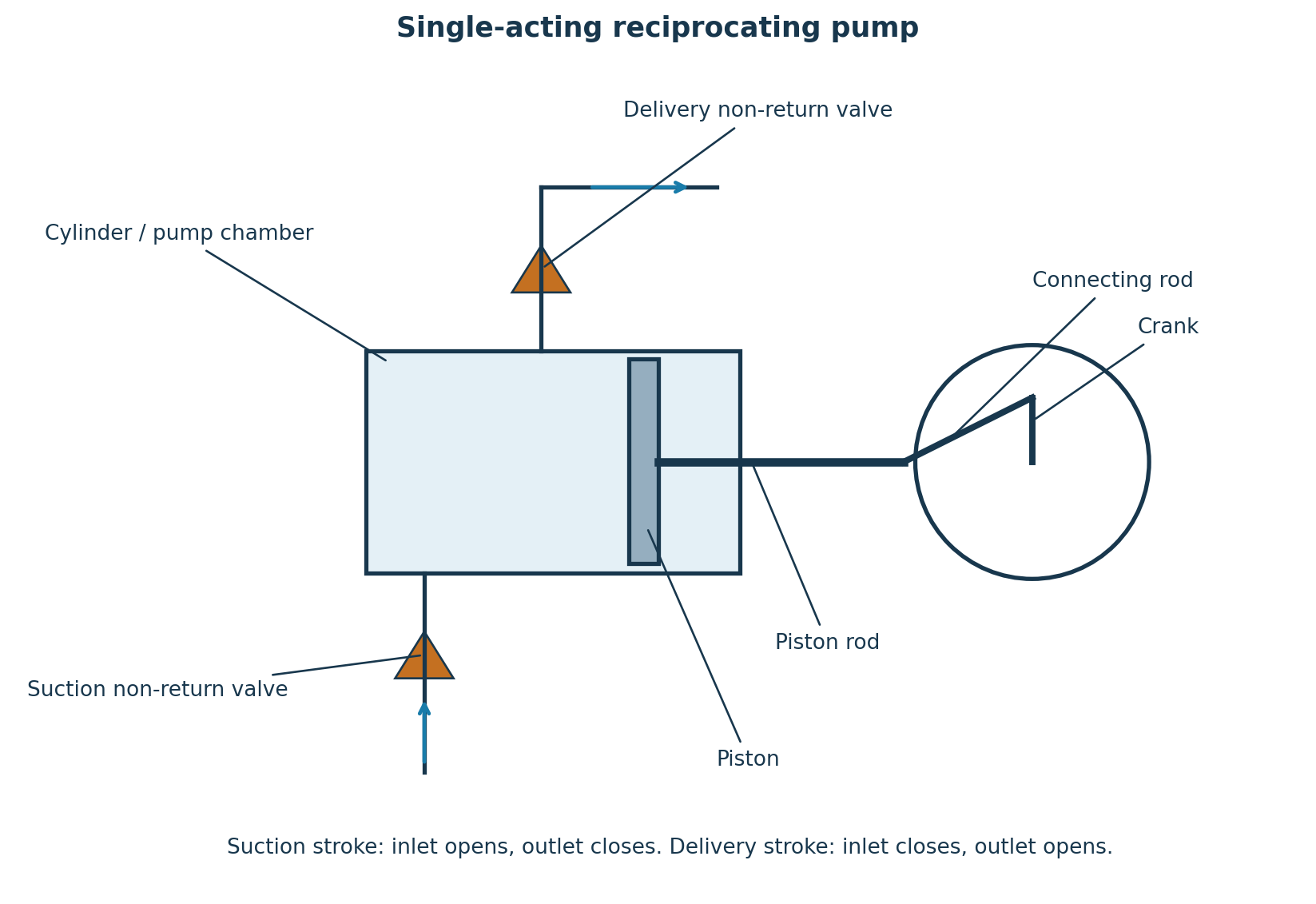
Question 8(c)
Explain the four components of a centrifugal pump.
(8 marks)
Answer
| Component | Function |
|---|---|
| Impeller | Rotating vanes transfer mechanical energy from the shaft to the liquid, increasing its velocity and energy. |
| Casing / volute | Collects the impeller discharge and guides it towards the outlet; its expanding passage converts part of the velocity energy into pressure. |
| Suction pipe and inlet assembly | Convey water from the source to the impeller eye. A strainer excludes debris and, where fitted, a foot valve helps retain prime. |
| Delivery pipe | Conveys water under pressure from the casing outlet to the required destination; the delivery valve controls or isolates flow. |
References for further study
- Kenya Occupational Safety and Health Act, 2007 — employer and employee duties, sections 6 and 13.
- Health and Safety Executive: construction fire safety — extinguisher selection and precautions.