PROJECT TITLE: MICROCONTROLLER BASED MOTOR SPEED CONTROLLER INCORPORATING IR SENSOR

PROJECT TITLE: MICROCONTROLLER BASED MOTOR SPEED CONTROLLER INCORPORATING IR SENSOR
| INSTITUTE …………
TRADE PROJECT COURSE NAME: DIPLOMA IN ELECTRICAL AND ELECTRONIC ENGINEERING (POWER)
PROJECT TITLE: MICROCONTROLLER BASED MOTOR SPEED CONTROLLER INCORPORATING IR SENSOR
NAME: …………………………………………………..
INDEX:…………………………………………..
SUPERVISOR: ……………………………………………..
PRESENTED TO: KENYA NATIONAL EXAMINATION COUNCIL
DATE OF PRESENTRATION: …………………………………………….. |
DEDICATION
I dedicate this project to my entire family members i.e. my father and mum
ACKNOWLEDGEMENT
Highly appreciate the contribution of my supervisor ………………………. for guiding me on coming p the project.
Secondly are my parents Mr. and Mrs……………………………… for their encouragement and financial support in completing the project.
Last but not least I would like to thank my friends ……………………………………. for giving encouragement and assistance where the need raised.
ABSTRACT/SYNOPIS
The project has incorporated the zero contact tachometer which provides the speeds of any rotating object e.g. a motor, flywheel etc. in this project I have used a microcontroller to process the input which is from the IR sensor and displays it on the LCD. The project will measure speed of any rotating object starting from 100rpm to 10000rpm
CHAPTER ONE
INTRODUCTION
This system accurately controls microcontroller-based motor speed using IR sensor. The system uses an 8051-family microcontroller to achieve this purpose.
The project constantly monitors the motor speed using IR sensor. The sensor is used to keep track of fun motor rotation and measure its revolution per minutes. The sensor is interfaced with the microcontroller then calculates motor speeds on signals provided by the sensor.
An LCD display is interfaced with the microcontroller which displays the status of the system along with modulation to keep the motor running around the desired speed through motor drive. The system uses matrix keypad which has on and off buttons where the on button is clicked to start the motor and then the motor run in both clockwise and anticlockwise direction. Thus, the speed of the motor can be increased or decreased in clockwise or anticlockwise direction with help of IR sensor.
AIM
The aim of the project is to design, construct and test microcontroller-based motor speed controller incorporating IR sensor.
OBJECTIVES:
i. To monitor the speed of the motor using IR sensor.
ii. To use a matrix keypad which has on and off buttons used to start and stop the motor.
iii. To provide a sensing system that senses when there is a fault.
BLOCK DIAGRAM
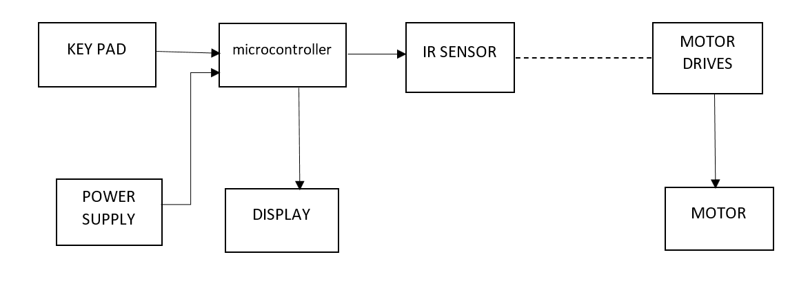
BLOCK DIAGRAM DESCRIPTION
- POWER SUPPLY
This converts 240v a.c mins to a stable 12v d.c. it comprises of a step down transformer for stepping down the voltage from 240 a.c to 12v d.c a bridge rectifier for IC to stabilize the power bang supplied.
- IR SENSOR.
An infrared sensor is an electronic instrument that is used to sense certain characteristic of its surrounding. It does this emitting or detecting infrared radiation. In this case it is used to detect the motion or speed of the motor.
- Motor drive
The function of the motor drive is to take a low-current control signal then turn it into signal that can drive the monitor i.e. amplifiers current.
- Key pad
This is a matrix keypad which has on and off button used to start and stop the motor
- Microcontroller
Provides input to the infrared sensor and display unit. It also manipulates motor speeds based on signals provided by sensor.
- Display unit
This is an LCD interfaced with the microcontroller which displays the status of the system along with motor speed.
- Motor
It’s a rotary electrical machine that converts direct current electrical energy into mechanical energy.
PROJECT SPECIFICATIONS
- Supply volatage 240A.C
- Operating volatage 12v D.C
- Operating current 500µA
- Infared-transmitter frequency 30Khz
- Motor speed ranges 77 – 1500 r.p.m
- Motor rating 80 watts
CHAPTER TWO
2.0 THEORETICAL ANALYSIS/LITERATURE REVIEW
2.1 INTRODUCTION
In this chapter the project lays ground for its operation by reviewing all the information concerning different circuits concepts.
Each and every block at least consists of a circuit. The operation of those circuits need to be explained.
In analyzing the circuits all the consists of a circuit all the concepts about the functionality and the type of the circuits have to be explained. It is of good practice to analysis other type of a particular circuit I n summary and the specific type that would be adopted to be explained in details
Since the design of the project is yet to be undertaken, only the component names symbols and abbreviations will be used. No values should be indicated.
2.1.1 POWER SUPPLY.
This is a unit that supplies power to the entire circuit at voltage. It consists of the following blocks

Fig. 2.1 power supply block diagram
TYPES OF POWER SUPPLIES
- Unregulated linear power supply
It consists of a step-down transformer, rectifier, filter capacitor and a bleeder resistor. The output voltage of this power supply type varies with the charge of input voltage and load current.
- Regulated linear power supply
This type of power supply is made up of a step-down transformer, rectifier, filter capacitor and a voltage regulator. Its output voltage is always constant regardless of changes in load current or its input supply voltage.
- Switch mode power supply
It is made up of two rectifiers, filter capacitors, serves transistor, regulator, blender resistor and a transformer. Due to presence of such components this type of power supply is more complicated compared to regulated and unregulated types.
- Uninterruptible power source that, in the case of power failure or fluctuations, allows through time for an orderly shutdown of the system or for stand by generator to start up. It consists of a bank of rechargeable batteries and power sensing and conditioning circuitry.
Therefore, the cost of constructing or purchasing this power supply is high compared to above mentioned types of supplies.
Regulated linear power supply will be used for the project since low power is need in the project circuitry. This power supply gives out a constant or stable D.V voltage as compared to unregulated type. It is less complex as compared to switch mode power supply and less bulky compared to uninterruptible power supply.

OPERATION
A.C power from the mains supply is a applied to the power supply through the primary winding of transformer (T1). The transformer lower supply voltage to the desired voltage according to the turn’s ratio, of the windings. The lowered voltage is applied to rectification unit (D1, D2, D3 and D4). Where it is converted to direct current (d.c) voltage. Filtering capacitor C1 and C2 grounds the altering current hence eliminating ripples to obtain pure d.c voltage. The voltage regulator (REG) maintains a constant output d.c voltage hence ensuring stability.
2.1.1 TRANSFORMER
A transformer is an electrical device which, by the principles of electromagnetic induction, transformer electrical rom one electric circuit to another without changing the frequency. The energy transfer usually take place with change of voltage and current. They are widely classified into two categories, which includes, step down and step up transformers. Step down transformers gives out less voltage and higher current than their input supply whereas for step up transfer gives out high voltage and less current compared to its input.
TYPES OF TRANSFORMERS
i. AUTOTRANFORMER
This is a transformer where primary and secondary windings are connected to each other in series both physically and magnetically on a single common coil voltage is varied according to the position of secondary tapping on the coil tapping.
ii. AIR CORE TRANSFORMER
This is a transformer where the both the primary and secondary windings are wound on magnetic strip where the flux linkage between primary and secondary windings is through the air. It has less mutual inductance compared to iron core transformer.
iii. Iron core transformer
It has both the primary and secondary windings would on multiple iron plate bunch which provides linkage path to the generated flux. It has a more mutual inductance than air transformer.
iv. Current transformer
This is a transformer that is used to measure alternating current. It provides a current into secondary winding which is proportional to the current units primary it scales large values of current to small, standardized values that are easily to handle measuring instruments such as clamp meter.
v. Power transformer
These transformers are big in size and suitable for high voltages power transfer applications. They are used in power generation stations and transmission substation
Iron core step down transformer will be employed in project since its efficiency is high compared to air core safes on space due to presence of magnetic core, this type of transformer has a high magnetic permeability hence less windings is needed to produce magnetic flux than in the case of air core transformer.

Fig 2.02 circuit diagram pf iron core transformer.
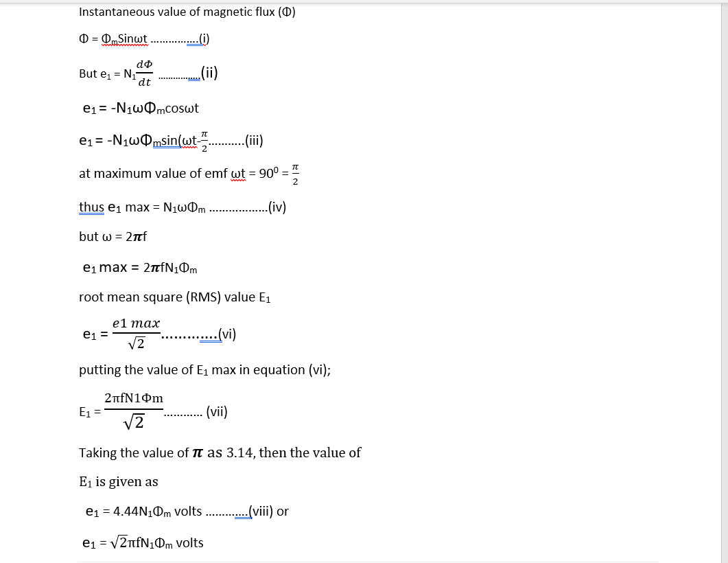
When alternating voltage is applied in the primary changing current produces a changing electromagnetic flux, at the same frequency. This flux induces an emf in the more turns, the induced e.m.f on the secondary [ coil is reduced.
E M F EQUATION OF A TRANSFORMER
Let Φm = maximum value of flux in weber.
F = the supply frequency in HZ
N1 = number of turns in the primary winding
N2 = number of turns in the secondary winding
E1 = EMF induced in the primary winding
E2 = EMF induced in the secondary winding
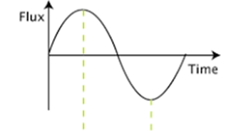
Fig 2.03 Graph of magnetic flux and time characteristics
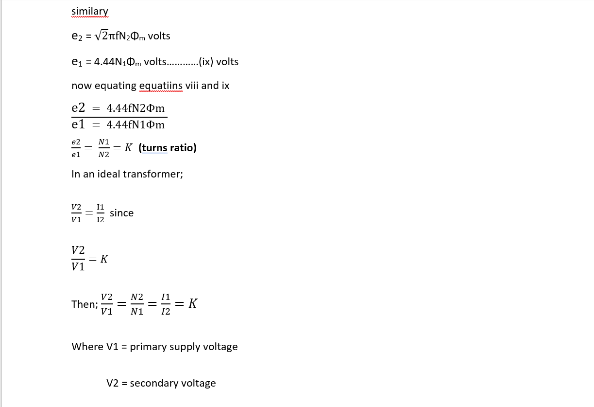
V2 = secondary voltage
2.1.3 RECTIFICATION UNIT
This is a unit of the power supply which perform the work of converting AC voltage form the transformer output to DC voltage. This is required because circuit for the project operate in dc voltage whereas the mains supply is ac. This unit is usually the arrangement of diodes or thyristors. Diodes are used in unicontrolled rectifiers whiule thyristors are used where the rectifier output voltage is to be controlled.
(i) Half wave rectifier
This is a simple type of rectifier madfe of single diode or thyristor which is connected in series with load. It only rectifiers the positive half of the ac input for which the diode becomes forward biased.
(ii) Full wave center-tapped rectifier
This is a type of rectifier which uses two diodesd and a transformer center tapped secondary winding.
During posive half cycle the first diode becomes forward based and allows current flow to the load. During the negative half cycle, the first diode becomes reverse biased while the second one becomes forward biased and allows current flow to the load. The center tapping of secondary provides the return path for the rectified voltage. The necessity of transformer with centre tapping secondary makes the circuit more costlier.
(iii) Full wave bridge rectifier
For this type of rectifier unit four diodes are arranged in a systematic form so as to rectify both the positive and negative half cycle of the transformer secondary voltage. It is usually more less costlier than center tapped rectifier.
Full wave bridge rectifier is employed for the project. This is because constant its output need not to be controlled. Also using the same transforms secondary voltage, bridge as compared to full wave centre tapped transformer rectifier. It utilises both positive and half waves from the transformer unlike in the case of half wave rectifier.
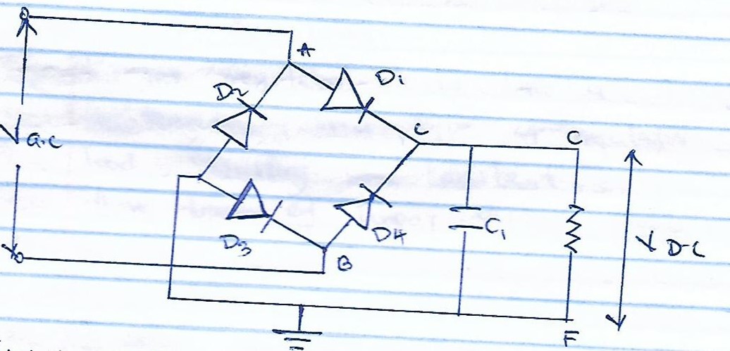 Fig 2.03 circuit diagram of a full wave bridge rectifier
2.1.4 VOLTAGE REGULATOR
It is a device which is used to stabilize the output voltage for a given circuit. It is designed in such a way that even if the amount of load is varied or its supply input voltage changer, it maintains its output voltage constant.
TYPES OF VOLTAGE REGULATORS
- Linear regulators
Linear regulators act like a voltage divider. The resistance of this type of regulator varies with the load resulting in constant output voltage. There are three types of linear voltage regulations.
- Series voltage regulator
A series voltage regulator uses a variable element placed in series with the load. By changing the resistance of that series element, the voltage dropped across it can be changed and the voltage across the load remains constant.
- Shunt voltage regulator
This regulator works by providing a path from the supplky voltage to ground through a variable resistance. The current through the shunt regulator is diverted away from thew load and flows uselessly to the load hence the voltage across the lod is maintained constant
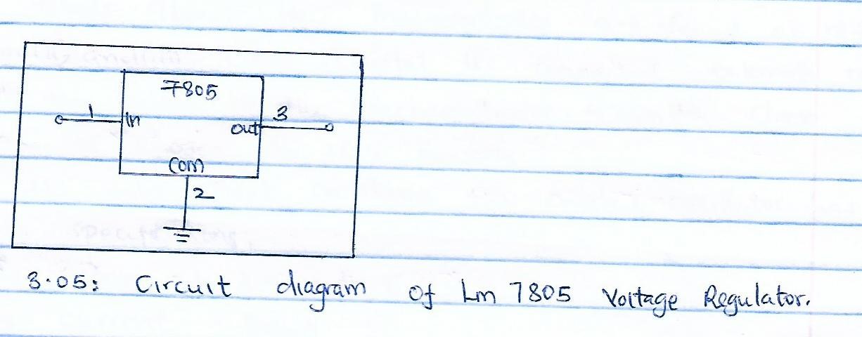
- Ic voltage regulator
It is a standard three pin linear voltage regulator which is designed to give a constant output voltage according to the model, they are named as LM78xx where xx represents the value of output voltage in volts.
- Switching voltage regulator
This type voltage regulator switches a series device on and off. This switches duty cycle sets the amount of charge transferred to the load. This is controlled by a feedback mechanism which is similar to that of alienator regulator
Switching regulatory are able to generate output voltage switching that are higher or lower than the input voltage or even of the opposite polarity.
This project intent to employ integrated circuits (I.C) voltage regulator because of the value of output regulator in IC form enables convenient operation of a microcontroller and a display unit by maintain the supply voltage at suitable level. By eliminating voltage fluctuations from the main supply ensures safety of the components against over voltage damages.
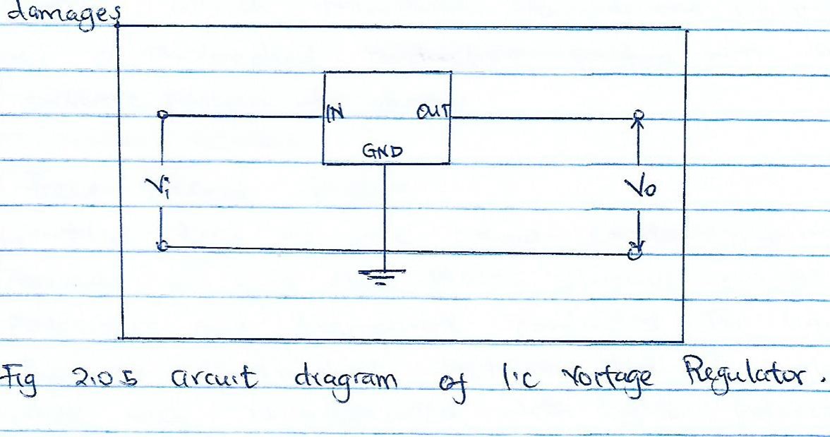 The I.c voltage regulator so designed by the manufacture in such away that iut can produce output voltage only when the input voltage exceeds its rated output by two volts. The output voltage value is maintained constant even if the load or input voltage varies. The output value
This is the process of converting AC supply into unidirectional D.C supply. This is required because the electronic circuits operate with d.c while the mains supply is a.c. these are several types of rectification
- Single phase rectifiers
- Three phase rectifiers
Single phase uncontrolled rectifiers
This type of rectifiers use the uncontrolled diode for rectifiers power becomes constant and changes of its magnitude or value depend on
- Half rectifiers
- Full wave rectifiers
Half rectifier
It is a simple type rectifier made with single diode which is connected in series with load.
For small power levels this type of rectifiers is commonly used

Fig 2.4 halfwave rectifier circuit and AC input waveform and resultant waveform.
During the positive half cycle of the AC input the diode becomes forward biased and current starts flowing through it. During the negative half of the AC input diode becomes reverse biased and current stops flowing through it. During the negative half of the AC input diode becomes reverse biased and current stops flowing through it. Output waveform across the load is shown in the fig above.
Because of high ripple content in the output, this type of rectifier is seldom used with pure resistive load.
FULL WAVE CENTRE TAPPED RECTIFIER
This type uses two diodes and a transformer with Centre tapped secondary winding. During the positive half cycle of the half AC diode D1 is forward biased and the current starts flowing to the load through it. During the negative half cycle of the input, diode D2 forward biases current starts flowing through D2 during this negative peak.

Fig 2.5 circuit diagram of full wave Centre tapped rectifier

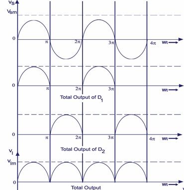
Full wave bridge rectifier
During the positive half of the input AC diodes D1 and D2 are forward biased and D3 and D4 are reversed biased. Thus load current flow though D1 and D2 diodes. During the negative half cycle of the input diodes D2 and D4 are forward biased and D1 and D2 are reversed biased, therefore load current flows through D3 and D4 diodes. This rectifier can produce almost double the output voltage as compared with full wave Centre- trapped transformer.

Fig 2.6 current flow positive half cycle
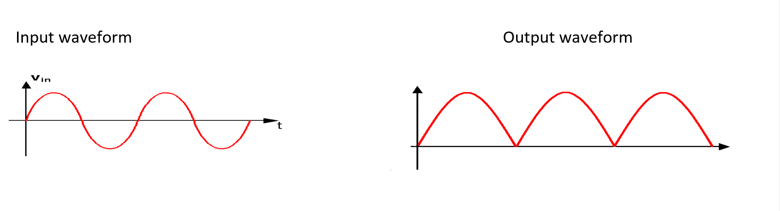

Fig 2.7 current flow negative half cycle
SINGLE PHASE HALF CONTROLLED RECTIFIER
Controlled rectifiers use thyristor in place of diode to control the output. By adjusting the triggering time of the thyristor, the project can control the voltage and current through loads and this process is termed as phase control method of rectification.

Fig 2.8 single phase Half controlled rectifier
SINGLE PHASE FULLY CONTROLLED FULLY CONTROLLED RECTIFIER
This type of power electronics base rectifier circuit is most popular one widely used in controlling the DC motors. This circuit is obtained by replacing all the diodes used in uncontrolled or half-controlled rectifiers with thyristors.

fig 2.9 single fully controlled fully controlled rectifier
the project employs the full wave bridge rectifier considering reason
- Smaller would be required
- Less rating per diode
- Suitable for voltage application
SMOOTHING
This is the process of removing rippled output of rectifier into a smooth dc power supply to be used to power electronics circuits without large levels of voltage regulations.
THERE ARE SEVERAL TYPES OF SMOOTHING CIRCUITRS.
- L-c
- R-c
- L-c-c
Shunt capacitor
A capacitor is used as the filter and this high value capacitor shunted or placed across the load impedance. This capacitor, when placed across rectifiers gets charged and stores the charged energy during the conduction period. When the rectifier is not conducting, this energy changed by the capacitors is delivered back to the load.
L-C
This is an inductor capacitor circuit where the capacitor is in parallel with the load and indicator in series with the load. Thus after the capacitor is fully charged, it discharges through the indicator thus this a filtration circuit.
R-C
This is resistor capacitor circuit; the resistance is connected in series with the load and capacitor in parallel. In this circuit the ripples have to be made to drop across the resistance instead of the laod resistance.

Fig 2.1.8 smoothing circuit
The smoothing circuit is achieved by use of electrolytic Aluminum capacitor which charges up when the voltage from the rectifier above that of a capacitor and then as a rectifier above that of a capacitor the required current from its stored charge. The diodes prevent backflow through the transformer.Capacitor are used to smooth the current and make it even. The project employs electrolytic capacitor for smoothing the current in power supplies.
Fig. 2.1.9 unsmoothed (dotted line) varying DC and smoothed DC
To remove ripple we use pie filter at the power output terminal since the rectified voltage waveform is a ripple wave it must be platen to obtain DC output.
Smoothing is not perfect due to the capacitor voltage falling a little as it discharge giving a small ripple voltage is satisfactory and the equation below gives the required value for the smoothing capacitor.
A larger capacitor will give less ripple. The capacitor value must be doubled when smoothing half wave DC
smoothing capacitor for 10% ripple.
Voltage Regulator
This is an integrated circuit that maintains the output of the power supply at a constant level inspite changes in load current or input voltage. There are several types of voltage regulators such as transistor series, fixed and variable regulators.The transistor series voltage regulator consists of Zener diode and a transistor connected in parallel with the load.

Fig1.6.Fixed Ic Voltage Regulator
Fixed Ic regulators provides a constant output voltage. Apopular example is the 7805 IC which provides a constant 5V. A fixed voltage regulator can be either a positive or negative one. They are same in design construction and operation only that the polarity of output voltage differs.
The system will use the third type I. ean adjustable voltage regulator . With it the output voltage can bevaried over range. These are two variations of the same positive and negative adjustable voltage regulator.

Fig1.7 variable/Adjustable voltage regulator
The resistors R1 and RL determine the output voltage. The resistor R2 is adjusted to generate to generate the output voltage range between 1.2v and 5.7v. The output voltage that is measured can be calculated using the equation.
V out=V ref(1+R2/R1)+IadjR2
LCD
A liquid crystal or LCD its definition from its name. it is a combination of two states of matter, the solid and the liquid. LCD uses a liquid crystal displays to produce a visible image. Liquid crystal displays to produce a visible image. Liquid crystal displays are super-thin technology that are generally used in laptop computer screen. TVS, CELLPHONES.
TYPES OF LCDS
There are many LCD displays types some are now cutting edge technology and other are older legacy types of display.
- Dynamic scattering LCD
This type of LCD consist of two glass plates with a liquid crystal fluid in between the two gplates. The back glass plate is coated with a thin layer of conductive material which transparent. However, the front glass plate has a photo etched conductive coating with seven segment pattern for display.
- Field effect display
In this type, nematic liquid crystal are involved. It consists of two glass plates, a liquid crystal fluid, polarizers and transparent conductors. The liquid crystal fluid is sandwiched between the two glass plates, where each is a associated with light polarizer. The light polarizers are placed at right angles to each other. In the absence of electrical excitation, the light coming through the front polarizer is rotated in the fluid in the fluid and passed through the rear polarizer. It is then reflected to the eye of the viewer by the black mirror. This project employs the LCD JHD162A which is efficient for the proposed embedded system in displaying data. The LCD jhd162a HAS THE FOLLOWING FEATURES
- 8-bit parallel data lines
- Operating temperature is indoor
- Single power driving voltage
- Positive transflective display
- 16 character X2 lines display construction

Fig 2.6.1 LCD block diagram
The liquid display has the distinct advantage of having a low power consumption than the LED. It is typically of the order of microwatts for the display in comparison to the some order to microwatts for the display in comparison to the some order of mill-wats for LEDS low power consumption requirement has it compatible with most integrated logic circuit. Its other advantages are its low cost and good contact.

Fig. 2.6.1 basic structure of an LCD
OPERATION
A liquid crystal cell consist of a thin layer of a liquid crystal sandwiched between two glass sheets with transparent electrodes deposited on their inside faces with both glass transparent, the cell is known as transmission type cell.
When one glass is transparent is transparent and other has a reflective type. The large does not produce any illumination of its own in fact it depends entry on illumination falling on it’s from an externally source for its visual effect.
2.2.0 MOTOR
An electric motor in an electric machine that converts electrical energy into mechanical energy. Most electrical motors operate through the interaction between the motor’s magnetic field and winding currents to generate force.
In certain applications, such as in regenerative braking with traction motors, electric motors can be used in reverse as generators in recover energy that might otherwise be lost as heat and friction. Electric motors can be powered by direct currents sources as from batteries, motors vehicle are rectifiers or by alternating current (AC) sources such as power grid, inverters or generators.
TYPES OF MOTORS
AC MOTOR
An AC motor is an electric motor driven by an alternating current (AC). The AC motor commonly consist of two basic parts , an outside stator having coils supplied with alternating current to produce a rotating magnetic field, and inside rotor attached to the output shaft producing a second rotating magnetic field. The rotor magnetic field magnatic field may be proiduced by permanent magnets, reluctances saliency, or DC or AC electrica;l windings.
COMPONETS OF AC MOTOR
- ROTOR
In an electric motor, the moving part is the rotor , which turns the shaft to deliver the mechanical power. The rotor usuallty has conductors laid into it that carry currents. Which interact with the magnetic field of the stator to generate the force that turn the shaft. In some rotor carry a permanent magnetic and the stator holds the conductors.
- STATOR
The stator is the stationary part of the motor’s electromagnetic circyuit and usually consist of other windings or permanent magnets. The stator core is made up of many thin metals sheets, called laminations which are used to reduced energy losses that would result if a solid core were used .
- AIR GAP
The distance between the rotor and stator is called the air gap. The auir gap has important effects and is generally a small as as possible , as a large gap has a strong negartive effects on performance. It is the main source of the low power factor at which motors operate.
- WINDINGS
Windings are wires that are laid in coils, usually wrapped around a laminated soft iron magnetic core so as to form magnetic poles when energized with current.
- CUMMUTATOR
A commutator is a mechanism used to switch the input of most DC machines and certain AC machines. It consist of slip-ring sagments insulated from each other and from the shaft. The motors armature current is supplied through stationary briushes in contact with the revolving commutators which causes required current reversal, and applies power to machine in an optimal manner as the rotor rotates from pole to pole.
DC MOTORS.
A DC motor is an electrical machine that converts direct current electrical energy into mechanical energy. The most common rely on the forces produced by magnetic fields. DC motor have internal mechanism either electromechanical or electronic to periodically change the direction of current flow in part of the motor.
Constructional, there is no basic difference between a dc generators to a dc motor. in fact, the same dc machine can be used interchangeably as a generator or as a motor
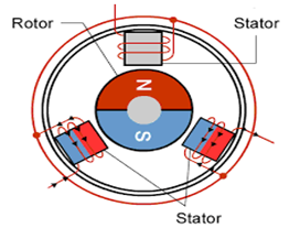
Fig 2.1 DC motor
This is a fixed set of magnets in the stator north (N) and south (S). it has an armature with one or more windings of insulated wire wrapped around a soft iron core. This iron core concentrates the field produced. The ends of the wire winding are connected to a commutator that powers up and energizes each armature coil. The strength of the electromagnetic field thus created, depends upon the amount of current passing through the coil, its size and the material around which it is wrapped.
A rotating magnetic field can be created by merely turning these coils on and off in a sequence. Now then this rotating exerts a force on the armature which sets it a rotation motion. By altering the direction and magnitude of the currents flowing through the coils, you can change the direction and magnitude of the magnitude of the magnetic produced by it.This project will use a dc motor since the power supply will be giving an output of 5V and the dc motor will be rated at 5V.
2.2 SENSORS
A sensor is a device that detects the changes in electrical or physical or other quantities and thereby produces an output an acknowledgement of change in the quantity.
2.2.1 TYPES OF SENSORS
TEMPERATURE SENSOR
A temperature sensor is the instrumentation equipment which is used to measure temperature or heat on the operating machine part. Temperature sensing is performed by equipment called thermocouple.
A thermocouple is a temperature measuring device consisting pof dissimilar conductors that contact each other at one or more points. It produces a voltage when the temperature of one of the points differs from the reference temperature at other parts of the circuit.
Thermocouples are simple, resilient and can used over a wide range of temperatures (from -330oF to 4170F) (-2000C to 23000C)) and permit great precision
Thermocouples are available in different combinations of metals or calibrations. The most common types are used in high temperature applications.
ULTRASONIC SENSOR
An ultrasonic sensor detects the presence of a target object and measures the distance between the sensor and the object by sending a beam of ultrasound from the emitter and detecting a reflection of the beam from the object with sensor.
The sensor calculates the exact distance between the sensor and the target object by computing the time that the beam has travelled, at the speed of sound, between emission and detection. A through scan model has an independent emitter and receiver that together detect the presence of a target object when the ultrasonic waves are either decreased or blocked by a target object.
TOUCH SENSOR
A touch sensor is a type of equipment that captures and records physical touch or embrace on a device object. It also referred to as touch sector.
A touch sensor primary works when an object or individual gets in physical contact with it touch sensors very sensitive and are often able to respond differently to different kinds of touch e.g. tapping, swiping and punching touch sensors are used in consumers device such as smartphones and tablet computers.
For example, when navigating through a smartphone or using application, the touch sensors capture the human touches or the applied pressure across the screen.
IR SENSOR
IR sensor are photo chips having a photocell which are used to emit and detect the infrared light. IR sensors, are generally used for designing remote control technology. They can also be used to detect obstacles of robotic vehicles for controlling purposes, also they are used for night vision.
Some of the reasons for using the IR sensor include: they provide secured communication due to line of sight point to point mode of communication, their power consumption is low, they need no contact with the product being sensed, their response time is faster than thermocouple, no corrosion or oxidation can affect the accuracy of infrared sensor, and in motion sensors detect motion in daytime and night time reliably.
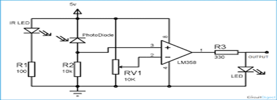
Fig2.1 sensor circuit design
The sensor unit consist of IR transmitter and IR receiver. An IR LED is used as the transmitter and photo diode is used as the receiver. A reflective type of IR sensor is used in this project. In this type the IR transmitter and receiver are place side-by-side.
The IR transmitter circuit is very simple. The anode of the IR transmitter is connected to power supply and the cathode is connected to ground through a current limiting resistor R1. Thus, the IR transmitter starts emitting infrared rays to the motor.
IR receives used in the project is a photo diode and it must be connected in reverse bias. The negative terminal or cathode is connected to the power supply and the positive terminal or anode is connected to ground through a current limiting resistor.
And finally the output of the IR transmitter circuit is very simple. The anode of the IR transmitter is connected to power supply and the cathode is connected to ground through a current limiting resistor R1. Thus, the IR transmitter starts emitting infrared rays to the motor.
IR receives used in the project is a photo diode and it must be connected in reverse bias. The negative terminal or cathode is connected to the power supply and the positive terminal or anode is connected to ground through a current limiting resistor.
And finally the output of the IR sensor is given to the sensor is given to the comparator compares the input from the IR receiver with a reference value. (Which is given through a R3 potential meter). If the input from the IR receiver is greater than the reference value, the output of the comparator will be high or else the output will be low.
2.4 MICROCONTROLLER
A microcontroller unit is am small computer on a single integrated circuit. In modern terminology. It is similar to, but less sophisticated than, a system on a chip or SoC; an SoC may include a microntroller as one of its components. A microcontroller contains CPUs (processor core) along with memory in the form of input/output peripherals.
2.4.1 TYPES OF MICROCONTROLLER
THE 8031 MICROCONTROLLER
This chip is often referred to as ROM less 8051 since it has OKB of on-chip ROM. To use this chip therefore you must add an external ROM to it. The external ROM must contain the program that the 8031 will fetch and execute.
Centrally 8051 on which the limited to only 4KB of code. The ROM contains the program attached to the 8051 can be as 6KB. In the process of adding external ROM to 8031, you will lose two ports hence leaving you with only two ports for input output operations. To solve this problem external input output is added to 8032.
THE 8052 MICROCONTROLLERS
It has got standard features of the 8051 as well as an extra 126 bytes of RAM and three timers. It also has 8bit on-chip program. ROM instead of 4KB. Therefore 8051 is a subject of 8052 and thus all programs written for the 8051 will run on 8052 but the reverse is not true.
The 8051 MICRONTROLLER
In this project Intel 8051 microcontroller will be used. For measuring the revelations per min of a rotation flywheel.
The 8051 microcontroller here does two jobs and they are:-
- Count the number of negative going pulses available at its T1 pin (pins) as shown in fig 2.2 below
- Do necessary mathematics and display the count on the LCD
For the counting purpose both the timers of 8051 (timers 0 and timers 1) are used. Timer is configured as an 8BIT auto reload counter for registering the number of incoming zero going pulses and timer 0 is configured as a 16bit which generate the necessary 1 minute time span for timer 1 to count.
CHAPTER 3
INTRODUCTION
In this chapter the project design is carried out. The components used in the project have their values and specification that are documented in the electric data sheet table. From chapter (ll) stated formulae and the design consideration for every component device are used to calculate or determine the value or type of what is to be used in a particular project.
In design the value obtained may not be exactly the value of purchased. The project is prototype of area life system therefore to determine the component to be bought tolerance limits need to be considered. In this chapter the entire project is assembled as a complete circuit and its operation is explained.
For any design work and the construction therefore in this chapter the total cost of the project will be given.
POWER SUPPLY DESIGN
A power supply can be broken down to a series of blocks, each of which performs a particular function .
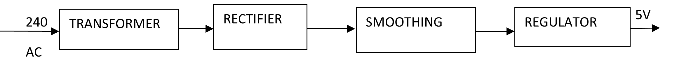
Figure 3.01 power supply
TRANSFORMER DESIGN
Laminated core transformer is the on used because it’s designed to work at low frequency. The laminated core transformer is used because of its low frequency operation
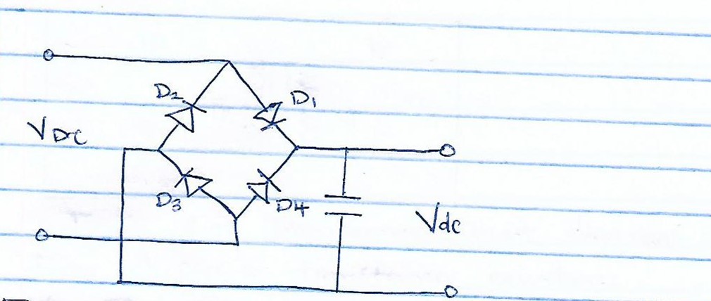
Figure 3.03 rectification cct design

Therefore IN4001 diodes will be purchased for the project since they can withstand the above condition
3.1.2 DESIGN OF SMOOTHING CAPACITOR (C1)
From the design equation
C= l/ϯ*v
From the data sheet whose reference is indicated in (V) the rated voltage for the capacitor is given as 10volts ;current IR is 2.9A and 100Hz frequency
C =2.7/100*10
=2.7*10-3 F
=2700MF
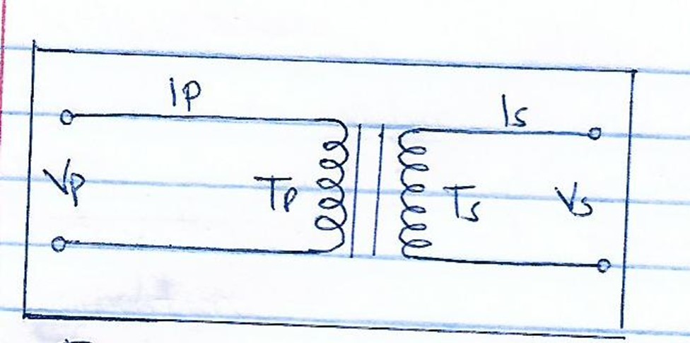
Figure 3.02 transformer circuit diagram
From chapter 2,transformer equation.

3.1.1 Design of Rectification Unit.
From the data sheet refered to number (IV) at material reference page.
Working peak inverse voltage = 50 V
Average rectifier output current=1.0A
Rms Reverse voltage ,VRMS=35V
Voltage drop=0.7 per diode.
But the output of the transformer which is to fed to the bridge rectifier is 12 volts. Therefore the diodes will be safe during negative half cycles of the supply. The nearest value of the available capacitor is 3300NF hence it will be purchased.

From the datasheet catalogue , the following are the specifications of the chosen IM 7805 voltage regulator input voltage range is 5V with an accuracy of I o.2 shortcut output current is 750MA.
More details about this type of voltage regulator can be obtained from reference number(VI).
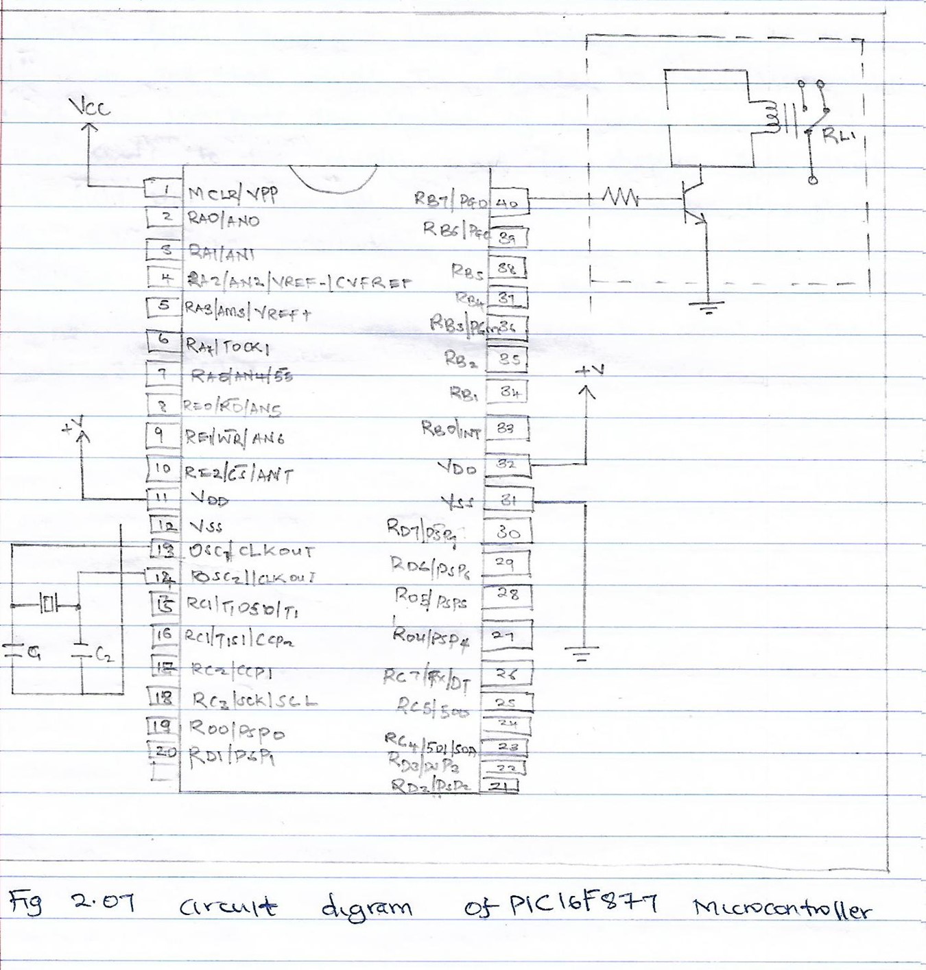
3.2 DESIGN OF MICROCONTROLLER
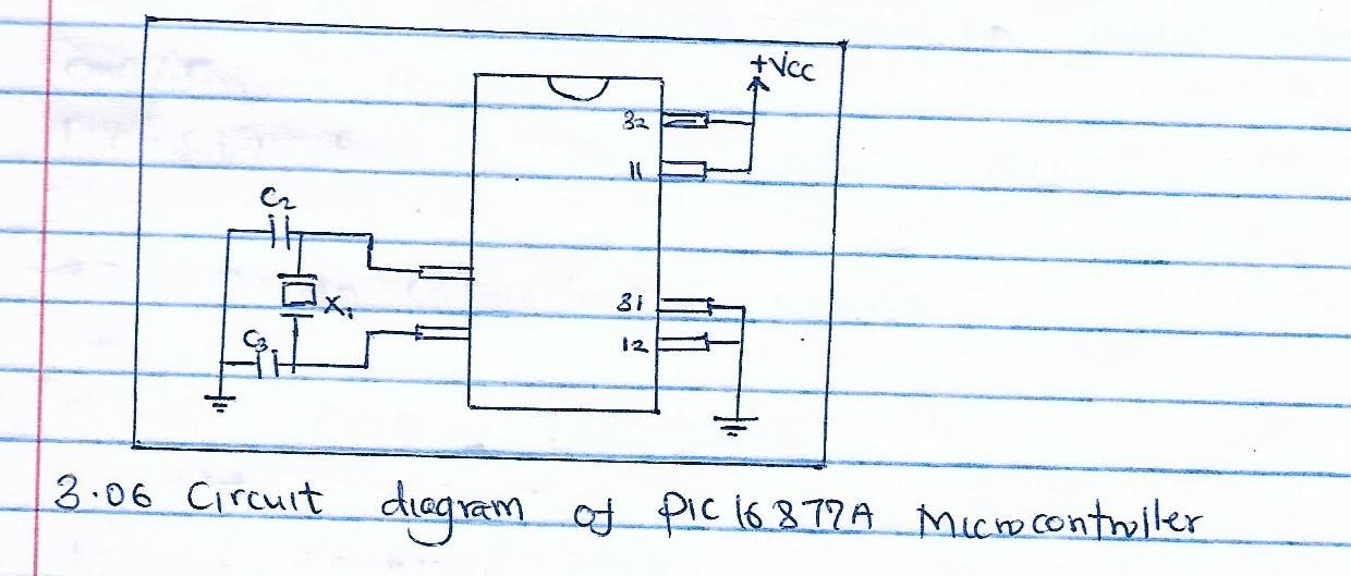
The chosen microcontroller is the PICI^*&&A. it is a 40 pin microcontroller which micriship describes as powerful based on having a 200nanosecond instruction speed.
From the data sheet , the PICI6877A has the following specification.
143 Kilobytes program memory.
368 bytes Ram size.
256 bytes EEPROM size.
10-bit up to 8 channel Analogue –to-digital converter. Universal synchronous asynchronous receiver transmitter (USART/SCI) with a bit address defection.
Operating voltage range :2V to 5.5V
More details about this microcontroller are found on reference number II and iii clock crystal is connected externally to provide the pulse to the microcontroller. A 20MHz clock crystal is chosen for this purpose.
From the data sheet catalogue the crystal oscillator has the supply voltage of 4.94 V to 5.46V
Supply current I 50A
More of the specification found on www.datasheetcatalog.com/frequency controls .INC
But supply from the power supply is 5V.
3.3.0 DESIGN CAPACITORS C2 and C3
C2=C3
C =1/Vx F (obtained from chap 2)
I =80mA;V=SV,f = 20mH
C= 0.8/5x20x106
I = 80mA
F=20MH
C= 0.8/5x20x106 =8No-9 F
The nearest value of capacitors to be purchased.
3.4 DISPLAY UNIT
A chosen display unit is an LCD type. It displays all letters of the alphabe,punctuatution marks ,mathematical symbols and as well as the numbers . it is a 16 x2 (i.e 2lines and 16 characters) display with each charcter made up of 5 x 8 dots.
The data sheet specifications are given below;
LCD operation voltage VOP =4.5 V
Maximum supply voltage VOld= VSS(max/min)=5.5V
LCD current consumption (NO B/L) Idd=1.5 mA
Backlight current consumption LED/edge =40mA
Input voltage Vin=Vdd +0.3V(max) more details about the LED are found on the (vii) of the reference.
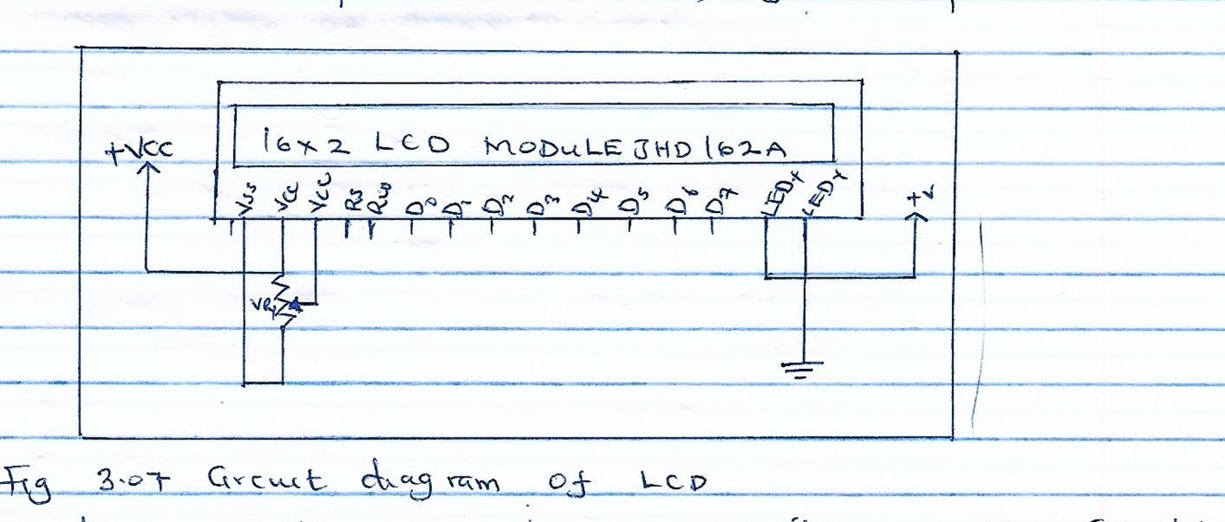
The diagram of the chosen LCD is compatible with the circuits power supply. The adjustments of the LCD is made using potentiometer VR, in whose value is chosen as 10Ksh from the datasheet.
I=Y/R
I=Vcc/R
=5/1000 A-0.5mA
Power dispated =I2R
=0.0005)2 x 10000
=2.5MW
Hence the current level is safe.
CIRCUIT DIAGRAM OF MOTOR SPEED CONTROL USING IR SENSOR INCORPORATING MICROCONTROLLER

TEST AND RESULT TABLE

PROJECT OPERATION
From the power supply A.c voltage is switched ON. It is stepped down by the step-down transformer and after that it goes to a bridge rectifier and the goes to the smoothing capacitor which are in parallel removing the pulse and then getting rid of D.C ripples . after that the voltage regulators IC supplies the circuit with stable 5Volts DC>
For the signal flow it starts from the remote which transmits infrared rays which are sensed by the IR sensor c infrared recedes module which the transits a signal to the microcontroller which reads the content of the infrared receiver which the displays on the LCD the on and off instructions and speed selection for the motor. The field effect transits switches the motor . variable resistors adjust the contrast of the liquid crystal display.
3.12 CONCLUTION
FROM THE TEST TABLE WE CAN CONDUCT THAT THE DISTANCE AT WHICH THE MOTOR IS TO BE CONTROLLED MUST BR FAR FROM the point of working. Also transmission frequency should be checked on as the motor arrive is coupled with the regulator to and in control of power supply to the motor.
3.13 RECOMMENDATION
After carrying out the project and testing I would like to recommend whoever will be working on the project in the future to do more design on the motor part so as to detect easily the direction and speed of the motor , also the remote to be abolished and instead wiresly using a mobile phone.
Also some improvement can be done in replacing L2930 motor drive IC with motor shield this is because L2930 can only control 2 motors while shield can even control servo motor and its also more programmed.
3.14 COMPONENTS AND DEVICES COSTS

3.15 OTHER COSTS