Power Production Systems — June/July 2024
KNEC Diploma in Mechanical Engineering — Module III. Paper code: 2502/305. Time: 3 hours.
These independent revision answers are not official KNEC marking schemes. Attempt each question before reading its answer. All optional questions are included for study.
Plant option. Answer FIVE of the SEVEN questions. Each whole question carries 20 marks.
Steam calculations use absolute pressures unless another convention is stated. Boiler operation, inspection and testing answers are examination outlines; actual work follows the manufacturer’s procedure and the authorised examiner’s requirements.
Question 1(a)
(i) Highlight six statutory requirements of a steam boiler. (ii) With the aid of a diagram, describe the operation of a fire-tube boiler.
(8 marks)
Answer
(i) Examples under Kenya’s Occupational Safety and Health Act, section 67:
- Sound construction, suitable material and adequate strength, maintained properly.
- An effective safety valve protected from unauthorised adjustment.
- An effective steam-pressure gauge showing the permissible pressure.
- A suitable means of indicating water level.
- A suitable steam stop valve and provision for examination and cleaning.
- Examination by an authorised person, with the required report and permissible working pressure recorded.
(ii) Fire-tube boiler operation:
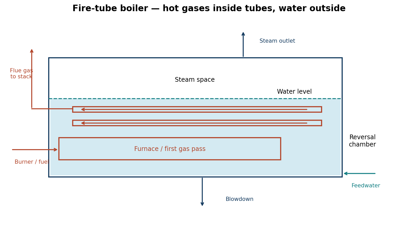
Fuel burns with air in the furnace. Hot gases travel through the furnace and return tubes before leaving through the flue. Heat passes through the tube walls to the surrounding water, producing steam that collects above the water level and leaves through the steam outlet. Feedwater replaces the water evaporated; controls maintain water level and pressure, while safety valves limit overpressure.
Question 1(b)
(i) Outline three types of steam plants. (ii) With the aid of a diagram, describe the circuits of a steam plant.
(12 marks)
Answer
| Type, classified by principal output | Outline |
|---|---|
| Power-only condensing plant | Steam expands through a turbine and exhausts to a condenser to maximise power output. |
| Process-steam plant | Produces steam primarily for industrial heating, drying, sterilisation or other processes. |
| Combined heat and power plant | Produces useful shaft/electrical power and supplies useful steam or heat, for example from a back-pressure or extraction turbine. |
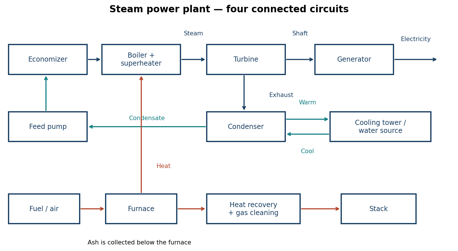
| Circuit | Flow and purpose |
|---|---|
| Water and steam | Condenser → feed pump → economizer → boiler → superheater → turbine → condenser. The turbine drives the generator. |
| Fuel and ash | Fuel handling feeds the furnace; combustion releases heat and ash is collected and removed. |
| Air and flue gas | Air passes through the air preheater to the furnace. Gas passes through heat-recovery surfaces and gas cleaning equipment before discharge through the stack. |
| Cooling water | Cooling water absorbs heat in the condenser and rejects it to a cooling tower or suitable cooling-water source. It is separate from the steam circuit. |
Question 2(a)
(i) Highlight five weekly maintenance practices carried out on a boiler. (ii) Outline the procedure for carrying out a boiler blow down.
(11 marks)
Answer
(i) Examples for a planned weekly maintenance programme; the manufacturer’s required daily and other checks still apply:
- Inspect boiler fittings, pipework and accessible joints for leakage or damage and record defects.
- Check and clean accessible strainers, filters and the feedwater system as specified, with isolation where required.
- Have the competent operator test the scheduled level-control, alarm and burner interlocks using the approved procedure.
- Review boiler/feedwater test results and check chemical-dosing and blowdown-control performance.
- Inspect burner/flue condition and review combustion readings; arrange authorised cleaning or adjustment where readings indicate poor performance.
(ii) Blowdown removes concentrated dissolved solids or settled sludge. For an examination outline:
- Confirm the type of blowdown, water-test result and approved boiler procedure; ensure the receiving blowdown vessel and discharge arrangements are ready.
- Check operating water level, feedwater availability and relevant pressure conditions. Keep people clear of hot discharge and protect against unintended operation.
- A trained operator operates the correct valves in the manufacturer’s specified order and for the specified brief duration or automatic-control setting. Monitor the water level throughout.
- Close and verify the valves as specified, check for leakage and restore normal water level and controls.
- Record the blowdown and follow-up water-test result. Excessive blowdown wastes treated water and heat.
Valve arrangements differ; this revision outline is not an operating sequence for an unidentified live boiler.
Question 2(b)
(i) Outline four methods of controlling pollution by sulphur dioxide arising from combustion of fuels. (ii) With the aid of a diagram, describe the operation of electrostatic precipitators as used in pollution control.
(9 marks)
Answer
- Select low-sulphur fuel or switch to a suitable lower-sulphur energy source.
- Remove sulphur from the fuel before combustion where practicable.
- Capture sulphur during combustion using an appropriate sorbent, such as in a suitably designed fluidised-bed system.
- Use flue-gas desulphurisation, for example a limestone scrubber, to remove SO₂ after combustion.
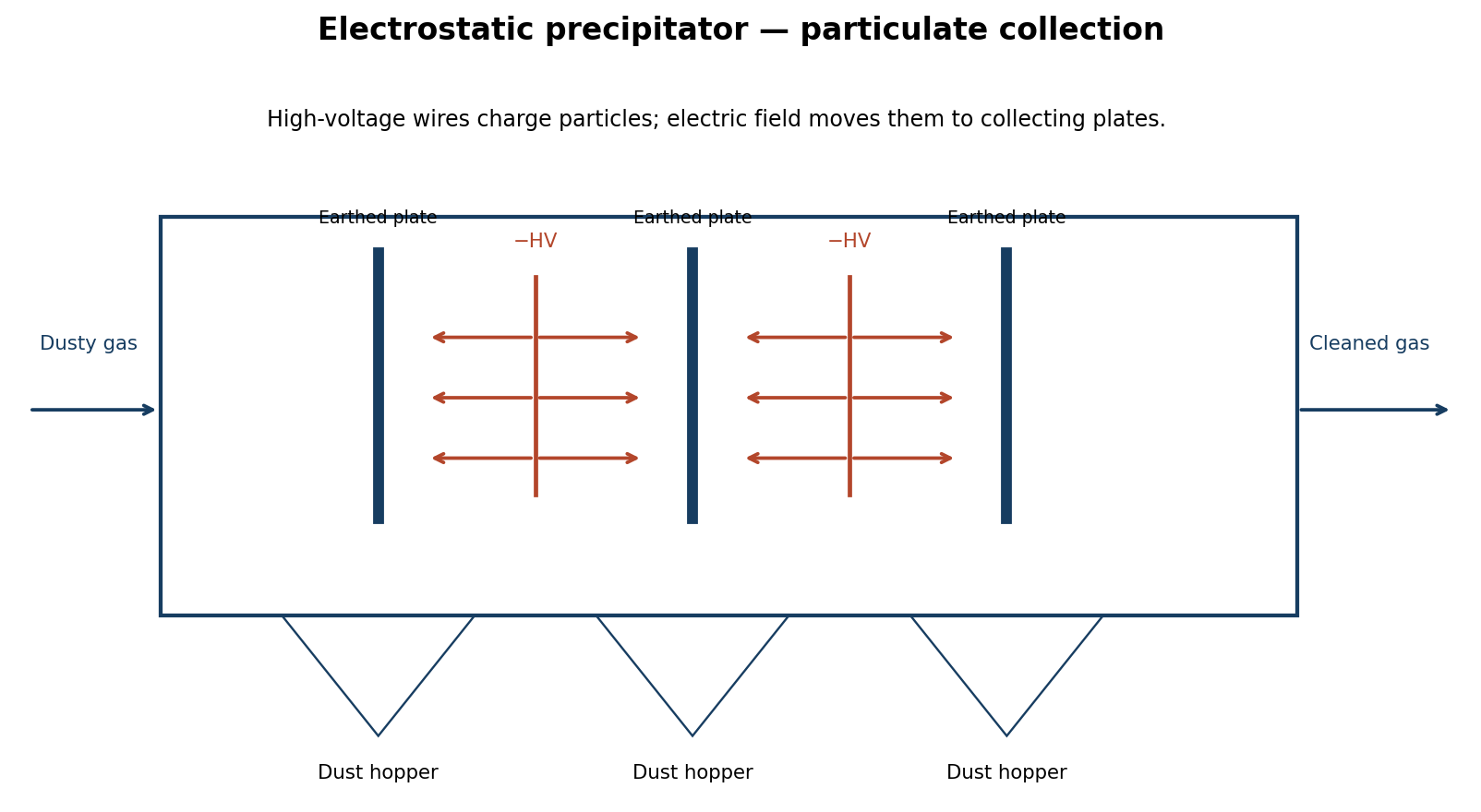
Dust-laden gas passes between high-voltage discharge electrodes and collecting plates. Ionisation charges particles, and the electric field moves them onto the plates. Rapping or washing removes the deposited material into collection hoppers. Cleaner gas leaves the unit; captured dust is handled separately.
Question 3(a)
(i) Explain four benefits of nuclear energy over other forms of energy. (ii) With the aid of a diagram, explain the operation of a nuclear power plant.
(9 marks)
Answer
- Very high fuel energy density: a small mass of fuel can supply a large amount of heat.
- Low direct greenhouse-gas emissions during electricity generation compared with fossil-fuel combustion.
- Reliable large-scale output can support continuous electricity demand.
- Fuel stocks occupy relatively little space, reducing the frequency and volume of fuel deliveries.
These benefits do not eliminate the need for radioactive-waste management, safety systems, cooling water and substantial capital investment.
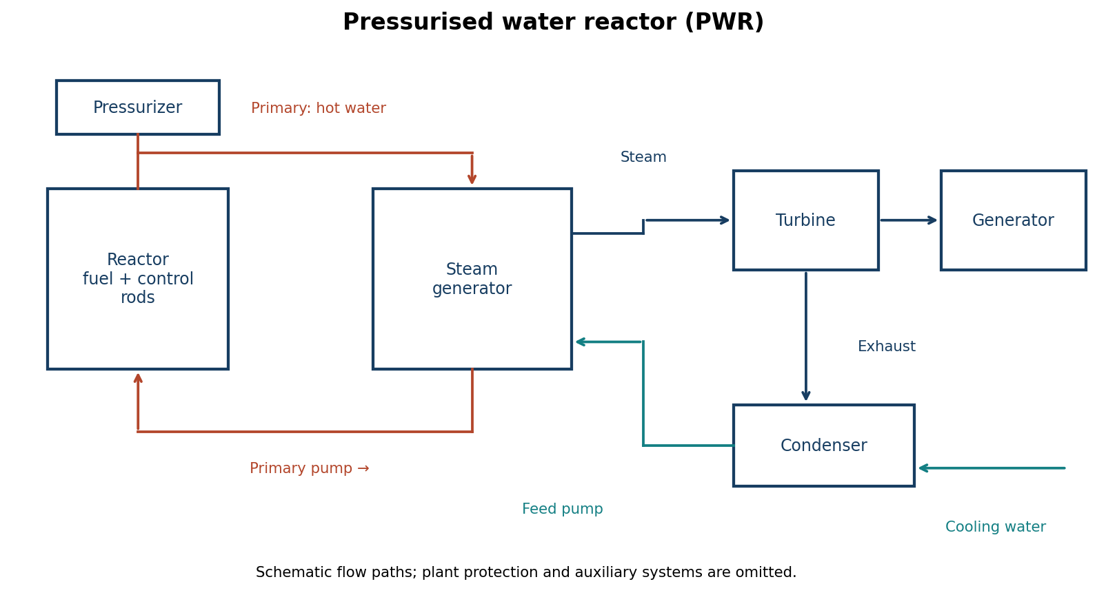
Controlled fission in the fuel releases heat. Coolant transports the heat to a steam generator, where a separate water circuit produces steam. Steam expands through the turbine, which drives an electrical generator. The condenser turns exhaust steam into water for return by the feed pump. Control rods regulate the chain reaction; shielding, containment and engineered cooling systems protect the plant and its surroundings.
Question 3(b)
(i) A boiler generates 30500 kg/h of steam at a pressure of 20 bar and temperature of 290°C. The temperature of water entering and leaving the economizer are 15°C and 90°C respectively. If the mass of fuel used is 3400 kg/h, determine the: (I) equivalent evaporation per kg of fuel; (II) thermal efficiency of the plant. Take calorific value of fuel C = 31000 kJ/kg and specific heat capacity of steam at constant pressure Cp = 2.1 kJ/kg K. (ii) Outline four benefits of energy monitoring and targeting.
(11 marks)
Answer
Assume the stated 20 bar is absolute. Use the given constant steam cp to estimate superheated enthalpy; feedwater enthalpy is approximated by 4.18T kJ/kg. Equivalent evaporation is from and at 100°C, using 2257 kJ/kg. Include the economizer in the overall plant boundary.
| Step | Working / result |
|---|---|
| Saturated properties at 20 bar | Tsat = 212.385°C; hg = 2798.384 kJ/kg. |
| Superheated steam enthalpy | hs = hg + 2.1(290 − Tsat) = 2961.377 kJ/kg. |
| Water enthalpy entering economizer | h15 ≈ 4.18 × 15 = 62.7 kJ/kg. |
| Steam/fuel ratio | 30500/3400 = 8.970588 kg steam/kg fuel. |
| Equivalent evaporation, whole plant | 8.970588(2961.377 − 62.7)/2257 = 11.521 kg/kg fuel. |
| Overall thermal efficiency | η = 30500(2961.377 − 62.7)/(3400 × 31000) = 83.88%. |
| Economizer heat gain | 30500 × 4.18(90 − 15) = 9,561,750 kJ/h. |
| If a boiler-only boundary is requested | Use h90 = 376.2 kJ/kg: equivalent evaporation = 10.275 kg/kg fuel and efficiency = 74.81%. This excludes the economizer heat gain. |
(ii) Monitoring and targeting:
- Establishes an energy-use baseline and realistic targets for the actual production output.
- Identifies avoidable losses, leaks and deteriorating equipment performance.
- Measures the savings achieved after efficiency improvements.
- Supports budgeting, cost control and reductions in fuel use and associated emissions.
Question 4(a)
With the aid of a diagram, describe the operation of the following in nuclear power plant: (i) pressured water reactor; (ii) boiling water reactor.
(9 marks)
Answer
(i) In a PWR, high pressure keeps primary coolant water liquid as it passes through the heated reactor core. A primary pump circulates it through a steam generator. A separate lower-pressure secondary loop boils to supply the turbine; the two fluids do not mix.
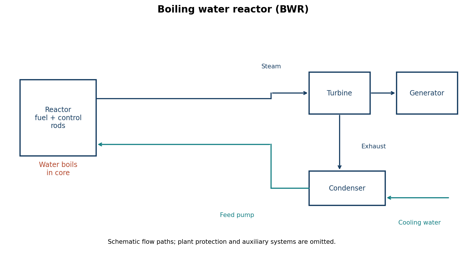
(ii) In a BWR, water boils in the reactor vessel. Steam is separated and dried before passing to the turbine. Exhaust steam is condensed and returned as feedwater. There is no separate primary-to-secondary steam generator as in the PWR.
Question 4(b)
(i) Outline the procedure for carrying out boiler pressure testing. (ii) With the aid of diagrams, describe the baffle type steam separator.
(11 marks)
Answer
- Plan the statutory examination with the authorised examiner and use the approved test specification. Shut down, cool, depressurise and isolate the boiler and connected energy sources.
- Prepare and inspect the pressure boundary and fittings. Fit calibrated gauges, a controlled hydraulic pump and the approved test fittings; vent trapped air while filling with suitable water.
- Raise pressure gradually to the examiner-approved test pressure. Hold for the specified period and examine for leakage, distortion or other defects from a safe position. Do not tighten or repair pressurised parts.
- Release pressure in a controlled manner, drain or preserve as appropriate, restore the correct fittings, and record the results and any required repairs before return to service.
Hydrostatic testing uses water, not a compressed-air substitute. Test pressure and duration come from the applicable specification and authorised examiner; they are not supplied in this question.
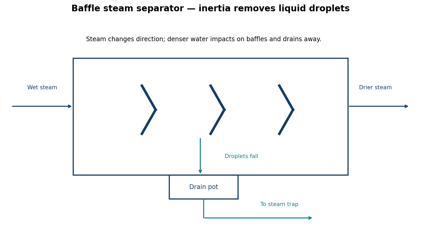
Wet steam is forced to change direction around the baffles. The heavier droplets cannot follow the gas path readily, strike the surfaces and coalesce. Water drains into a lower collecting space and is removed through a suitable trap. The remaining steam leaves through the outlet with reduced moisture content.
Question 5(a)
(i) Define the following as applied to steam: (I) saturated steam; (II) superheated steam; (III) latent heat of vapourisation. (ii) With the aid of a diagram, describe the procedure for determining the dryness fraction of steam by use of the following: (I) throttling calorimeter; (II) separating calorimeter.
(12 marks)
Answer
| Term | Meaning |
|---|---|
| Saturated steam | Vapour at the saturation temperature corresponding to its pressure; dry saturated steam has dryness fraction x = 1, while wet saturated steam includes liquid droplets. |
| Superheated steam | Steam at a temperature above the saturation temperature for its pressure. |
| Latent heat of vapourisation | The specific enthalpy increase hfg needed to change saturated liquid to dry saturated vapour at the same pressure. |
| Method | Procedure and relationship |
|---|---|
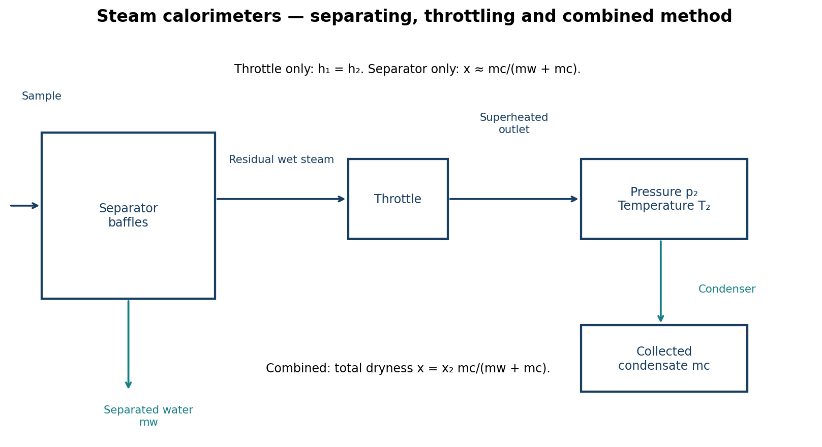
| Throttling | Measure inlet absolute pressure p₁ and outlet absolute pressure p₂ and temperature T₂. The insulated throttle has essentially no shaft work and negligible kinetic-energy change, so h₁ ≈ h₂. When outlet steam is demonstrably superheated, h₂ = hg(p₂) + cp[T₂ − Tsat(p₂)] and x = [h₂ − hf(p₁)]/hfg(p₁). |
| Separating | Pass a representative wet-steam sample through baffles so droplets fall into a measuring vessel. Collect separated water mw and condense and weigh the remaining steam mc over the same interval. If the residual steam is dry, x ≈ mc/(mw + mc). Residual wetness makes this assumption inaccurate. |
| Combined | First separate water mw, then throttle the residual sample to a superheated outlet. Determine its residual dryness x₂ by the throttling equation. If the downstream sample condenses to mass mc, total inlet dryness is x = x₂mc/(mw + mc). |
Question 5(b)
In a throttling calorimeter, steam is admitted at a pressure of 10 bar and discharged to the atmosphere at 110°C after throttling. If specific heat capacity of steam is 2.2 kJ/kg K, determine the dryness fraction of the steam.
(6 marks)
Answer
| Step | Working / result |
|---|---|
| Pressure convention | Assume inlet 10 bar absolute and atmospheric outlet 1.01325 bar. |
| Inlet saturated properties | hf = 762.683; hfg = 2014.437 kJ/kg. |
| Outlet enthalpy | h₂ = hg(atmosphere) + 2.2[110 − Tsat(atmosphere)] = 2697.588 kJ/kg. |
| Throttling balance | h₁ = h₂ = hf₁ + xhfg₁. |
| Dryness fraction | x = (h₂ − hf₁)/hfg₁ = 0.96052, approximately 96.05% dry. |
| If 10 bar denotes gauge pressure | Use inlet absolute pressure 11.01325 bar instead; x ≈ 0.95842. State the convention rather than mixing gauge and absolute properties. |
Question 5(c)
Outline two methods of idler boiler storage.
(2 marks)
Answer
| Method | Outline |
|---|---|
| Wet storage | After shutdown and cleaning, fill with appropriately treated, oxygen-controlled water under the approved preservation programme; exclude air and monitor the specified water chemistry. Suitable arrangements depend on expected storage duration and freezing risk. |
| Dry storage | After shutdown and cleaning, drain completely and dry the internal surfaces. Maintain a dry sealed environment using the specified desiccant or dry-air arrangement; inspect and renew protection periodically. Remove preservation materials and inspect before recommissioning. |
Question 6(a)
(i) Highlight four ways of increasing efficiency in a steam plant. (ii) Illustrate a typical steam power plant.
(9 marks)
Answer
- Recover flue-gas heat using a suitable economizer and air preheater.
- Maintain correct combustion and excess air, using measured combustion performance.
- Insulate hot surfaces and repair steam leaks and failed steam traps.
- Recover useful condensate and control blowdown to the necessary water-quality level.
| Circuit | Flow and purpose |
|---|---|
| Water and steam | Condenser → feed pump → economizer → boiler → superheater → turbine → condenser. The turbine drives the generator. |
| Fuel and ash | Fuel handling feeds the furnace; combustion releases heat and ash is collected and removed. |
| Air and flue gas | Air passes through the air preheater to the furnace. Gas passes through heat-recovery surfaces and gas cleaning equipment before discharge through the stack. |
| Cooling water | Cooling water absorbs heat in the condenser and rejects it to a cooling tower or suitable cooling-water source. It is separate from the steam circuit. |
Question 6(b)
(i) Explain three benefits of boiler feed water treatment. (ii) With the aid of a diagram, describe the process of demineralization of boiler feed water.
(11 marks)
Answer
- Reduces scale formation, preserving heat transfer and avoiding local overheating.
- Controls corrosion from dissolved gases and unsuitable water chemistry, extending equipment life.
- Limits foaming and carryover, improving steam purity and reducing deposits in downstream equipment.
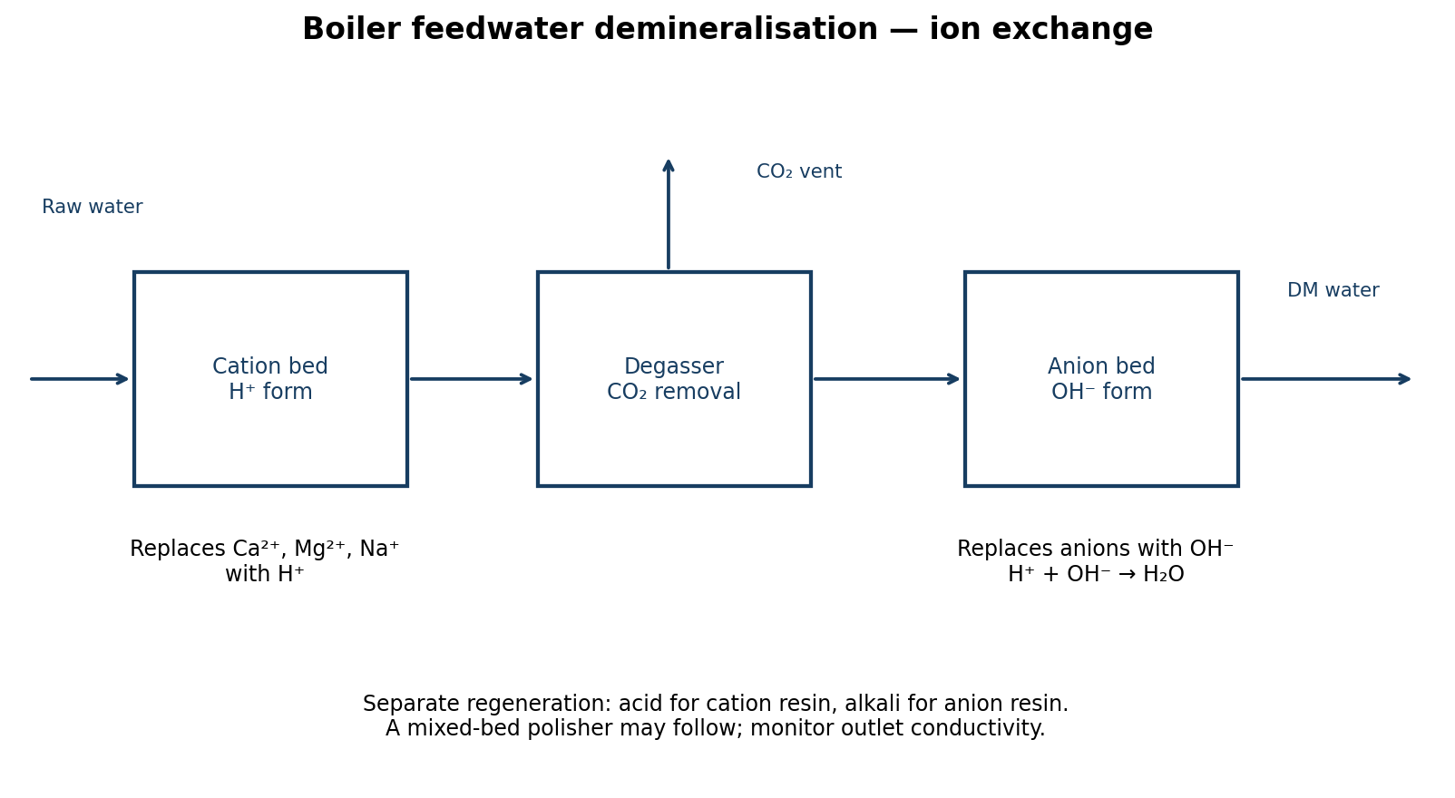
Raw water passes through a hydrogen-form cation-exchange resin, which replaces cations such as calcium and sodium with hydrogen ions. A degasser may remove carbon dioxide formed from bicarbonate. The anion bed exchanges dissolved anions for hydroxide ions; hydrogen and hydroxide combine to form water. A mixed-bed polisher may provide final purification. Conductivity and other required quality tests confirm performance; exhausted resins are regenerated separately using the specified acid and alkali procedures.
Question 7(a)
(i) Outline the procedure for carrying out internal inspection of a boiler. (ii) Highlight six routine maintenance checks carried out on a boiler fireside. (iii) Explain four merits of a water tube boiler over a fire tube boiler.
(12 marks)
Answer
(i) Internal inspection:
- Arrange the inspection and required permits with the authorised examiner; shut down, cool, depressurise and isolate fuel, electricity, steam and water connections.
- Drain and positively verify the safe isolated condition. Open access points only after confirming there is no pressure or hazardous temperature.
- Clean and prepare the surfaces. Any entry requires an appropriate confined-space system, atmosphere checks, supervision and rescue arrangements.
- Inspect drums, shells, tubes, stays, welds and joints for corrosion, erosion, scale, cracking, deformation and leakage. Record defects and arrange specified thickness testing or other examination.
- Complete repairs and the examiner’s requirements, restore fittings, carry out specified tests and document permission to return to service.
(ii) Fireside checks:
- Soot and ash deposits on heating surfaces.
- Burner condition, flame pattern and fuel distribution.
- Refractory lining, firebrick and furnace damage.
- Tube surfaces and tube-plate joints for leakage or overheating.
- Doors, seals, flue passages and dampers for leakage or obstruction.
- Fans, draught and combustion readings for correct performance.
(iii) Water-tube merits:
- Small-diameter pressure parts suit higher steam pressures.
- Large heating surface and circulation arrangements suit high evaporation rates.
- Lower water inventory generally permits faster raising of steam and response to load changes.
- The layout accommodates large furnace capacities and superheating arrangements efficiently.
Question 7(b)
With the aid of a diagram, describe the operation of the following: (i) tubular air-preheaters; (ii) inverted bucket steam trap.
(8 marks)
Answer
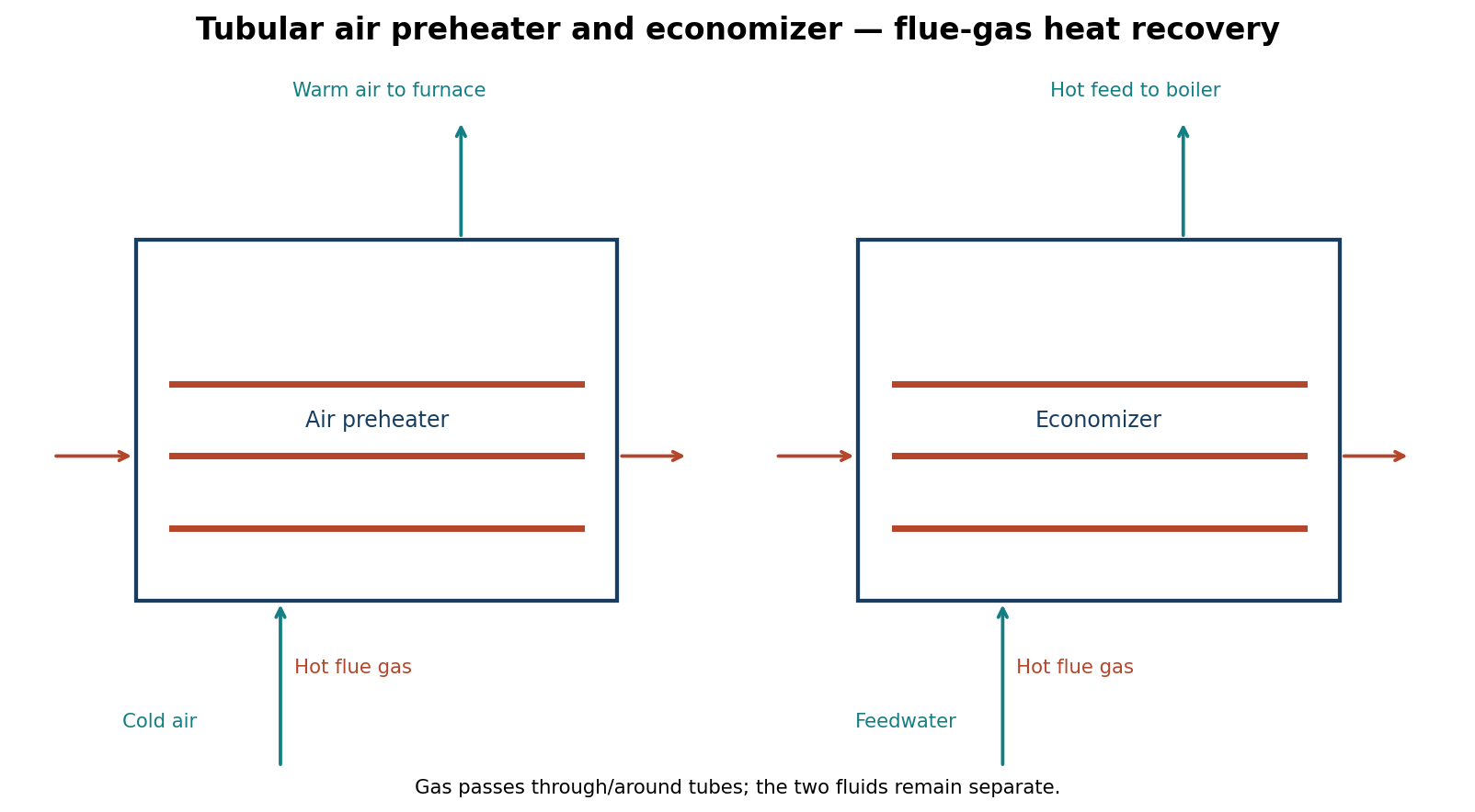
(i) Hot flue gas and incoming combustion air pass on opposite sides of the tube walls. Heat is transferred through the walls without mixing the fluids. Warmed air enters the furnace and reduces the fuel needed to maintain combustion temperature.
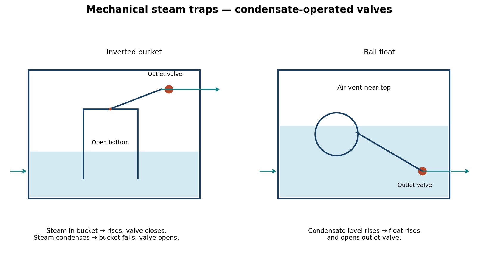
(ii) Condensate initially enters the inverted-bucket trap and discharges through an open outlet valve. Steam entering beneath the bucket makes it buoyant, so it rises and its linkage closes the outlet. As steam inside condenses and air vents through the small vent, buoyancy decreases; the bucket drops and opens the valve to discharge condensate. The trap must retain its water seal.