Fluid Mechanics and Thermodynamics — March/April 2024
KNEC Diploma in Mechanical Engineering — Module III. Paper code: 2502/304. Time: 3 hours.
These independent revision answers are not official KNEC marking schemes. Attempt each question before reading its answer. All optional questions are included for study.
Answer FIVE questions: TWO from Section A (Questions 1–3) and THREE from Section B (Questions 4–7). Each whole question carries 20 marks.
Printed data are retained. Question 1(c) contains inconsistent model-pump data; Question 3(b) prints viscosity as 15 × 10³ Pa s; Question 5(a) omits the outside film coefficient. Conditional interpretations are identified beside the relevant working.
Question 1(a)
(i) Explain the term “Dynamic Similarity”. (ii) State the Buckingham π Theorem.
(4 marks)
Answer
| Item | Answer |
|---|---|
| Dynamic similarity | Geometrically and kinematically similar flows are dynamically similar when the ratios of corresponding forces are equal. The relevant force ratios, expressed by dimensionless numbers such as Reynolds and Froude numbers, must match between model and prototype. |
| Buckingham π theorem | If a dimensionally homogeneous physical relation contains n variables involving k independent fundamental dimensions, it can be expressed using n − k independent dimensionless groups: F(π₁, π₂, …, πn−k) = 0. |
Question 1(b)
Show, by dimensional analysis, that the resistance R of a submerged body due to the velocity v of flow is given by the expression R = ρL²v² φ[(μ/(ρvL))(Lg/v²)], where ρ = mass density; μ = dynamic viscosity; L = length; g = gravitational acceleration.
(10 marks)
Answer
Use the six variables R, ρ, L, v, μ and g. There are three independent dimensions M, L and T, giving three π groups. Select ρ, v and L as repeating variables; each includes independent combinations of the fundamental dimensions.
| Group | Dimensional equations | Result |
|---|---|---|
| Π₁ = RρᵃvᵇLᶜ | [R] = MLT⁻². M: 1 + a = 0; T: −2 − b = 0; L: 1 − 3a + b + c = 0. Thus a = −1, b = −2, c = −2. | Π₁ = R/(ρv²L²). |
| Π₂ = μρᵃvᵇLᶜ | [μ] = ML⁻¹T⁻¹. M: 1 + a = 0; T: −1 − b = 0; L: −1 − 3a + b + c = 0. Thus a = −1, b = −1, c = −1. | Π₂ = μ/(ρvL) = 1/Re. |
| Π₃ = gρᵃvᵇLᶜ | [g] = LT⁻². M: a = 0; T: −2 − b = 0; L: 1 − 3a + b + c = 0. Thus a = 0, b = −2, c = 1. | Π₃ = gL/v² = 1/Fr². |
| Functional relation | F(Π₁,Π₂,Π₃) = 0 ⇒ Π₁ = Φ(Π₂,Π₃). | R = ρL²v² Φ[μ/(ρvL), gL/v²]. |
The two adjacent arguments in the printed expression are interpreted as two independent dimensionless arguments. Dimensional analysis does not justify replacing their dependence by dependence on their product alone. The function Φ must be established by experiment or further physical analysis.
Question 1(c)
The pumping process of an axial flow pump has its power P expressed as P = ρD⁵N³ φ[(H/D),(Q/(ND³))]. A model scaled to one-quarter the size of the prototype has the following characteristics: Pm = 3 kW, Qm = 2.5 m³/s, Hm = 15 m, Nm = 1200 rpm, Dm = 0.6 m. If the full size pump is to run at 1400 rpm, determine the: (i) power to drive the pump; (ii) head to be maintained by the pump.
(6 marks)
Answer
For geometrically similar pumps at corresponding operating points, using the same fluid and equal efficiency, adopt the conventional pump affinity laws P ∝ ρN³D⁵ and H ∝ N²D². The diameter scale is Dp/Dm = 4 and speed ratio is Np/Nm = 1400/1200 = 7/6.
| Quantity | Working | Result |
|---|---|---|
| Prototype diameter | Dp = 4 × 0.6 | 2.4 m |
| (i) Formal power | Pp = 3(7/6)³4⁵ | 4878.222 kW = 4.87822 MW |
| (ii) Formal head | Hp = 15(7/6)²4² | 326.667 m |
| Related flow scaling | Qp = 2.5(7/6)4³ | 186.667 m³/s |
Source-data check: the printed model flow is 2.5 m³/s. For water, its hydraulic power at 15 m head is ρgQH = 367.875 kW, which exceeds the stated 3 kW drive power. The dataset therefore cannot represent a physically possible water pump. The numerical answers above are formal affinity-law results. Also, the usual head similarity coefficient is gH/(N²D²); H/D in the printed function does not supply the conventional speed-dependent head law. These limitations must be stated rather than silently changing the data.
Question 2(a)
Two reservoirs are connected by a pipeline which is 100 mm diameter for the first 10 m and 150 mm in diameter for the remaining 20 m. The entrance and exit are sharp and the change in the section is sudden. The water surface in the upper reservoir is 10 m above that in the lower. The friction coefficient for both pipes is 0.015. Determine the rate of discharge in m³/s.
(10 marks)
Answer
Apply Bernoulli between the two reservoir surfaces, where velocities are negligible. Adopt the traditional examination friction convention hf = 4f(L/D)V²/(2g), sharp entrance coefficient 0.5 and exit coefficient 1. The sudden-enlargement loss is (V₁ − V₂)²/(2g).
| Step | Working / result |
|---|---|
| Areas | A₁ = π(0.100)²/4 = 0.007853982 m²; A₂ = π(0.150)²/4 = 0.017671459 m². |
| Continuity | V₁ = Q/A₁ and V₂ = Q/A₂. |
| Total available head | 10 = [0.5V₁² + 4(0.015)(10/0.1)V₁² + (V₁ − V₂)² + 4(0.015)(20/0.15)V₂² + V₂²]/(2g). |
| Collect Q² | 10 = 7094.688788 Q². |
| Discharge | Q = √(10/7094.688788) = 0.0375434 m³/s = 37.5434 litres/s. |
| Velocity check | V₁ = 4.78017 m/s; V₂ = 2.12452 m/s. |
| Head-loss check | Entrance 0.582315 + small-pipe friction 6.987779 + enlargement 0.359454 + large-pipe friction 1.840403 + exit 0.230050 = 10.0000 m. |
If 0.015 is instead a Darcy friction factor, the friction terms omit the factor 4 and the resulting discharge is 0.0645874 m³/s. State the convention; do not mix the two definitions.
Question 2(b)
The impeller of a centrifugal pump has external and internal diameters as 500 mm and 250 mm respectively. The width at outlet is 50 mm and the pump runs at 1200 rpm against a head of 48 m. The velocity of flow through the impeller is constant at 3 m/s. The vanes are set back at an angle of 40° at the outlet. Calculate the: (i) inlet vane angle; (ii) power required to drive the motor; (iii) manometric efficiency.
(10 marks)
Answer
Assume water of density 1000 kg/m³, radial entry without prewhirl, no blade blockage and angles measured from the tangent. Distinguish useful water power, impeller power and actual motor input.
| Step | Working / result |
|---|---|
| Peripheral speeds | u₁ = πD₁N/60 = 15.70796 m/s; u₂ = πD₂N/60 = 31.41593 m/s. |
| (i) Inlet vane angle | tanβ₁ = Vf/u₁ = 3/15.70796 ⇒ β₁ = 10.8125°. |
| Outlet whirl velocity | Vw₂ = u₂ − Vf cotβ₂ = 31.41593 − 3cot40° = 27.84067 m/s. |
| Discharge | Q = πD₂b₂Vf = π(0.5)(0.05)(3) = 0.23561945 m³/s. |
| Euler head | HE = (u₂Vw₂ − u₁Vw₁)/g = 89.15803 m, since Vw₁ = 0. |
| (ii) Power transferred by impeller | Pimp = ρQ u₂Vw₂ = 206.082 kW. This is the drive power if mechanical losses are neglected. |
| Useful water power | ρgQHm = 110.948 kW. This is not the motor input. |
| Actual electrical input | Pmotor,in = 206.082/(ηmechanical ηmotor) kW. These efficiencies are not supplied. |
| (iii) Manometric efficiency | ηman = Hm/HE = 48/89.15803 = 0.538370 = 53.8370%. |
Question 3(a)
Show that the discharge Q of a steady laminar flow between flat plates which are parallel is given by Q = Pbh³/(12μL), where P = pressure difference; L = length of plates; b = breadth; h = distance between the plates; μ = coefficient of dynamic viscosity.
(15 marks)
Answer
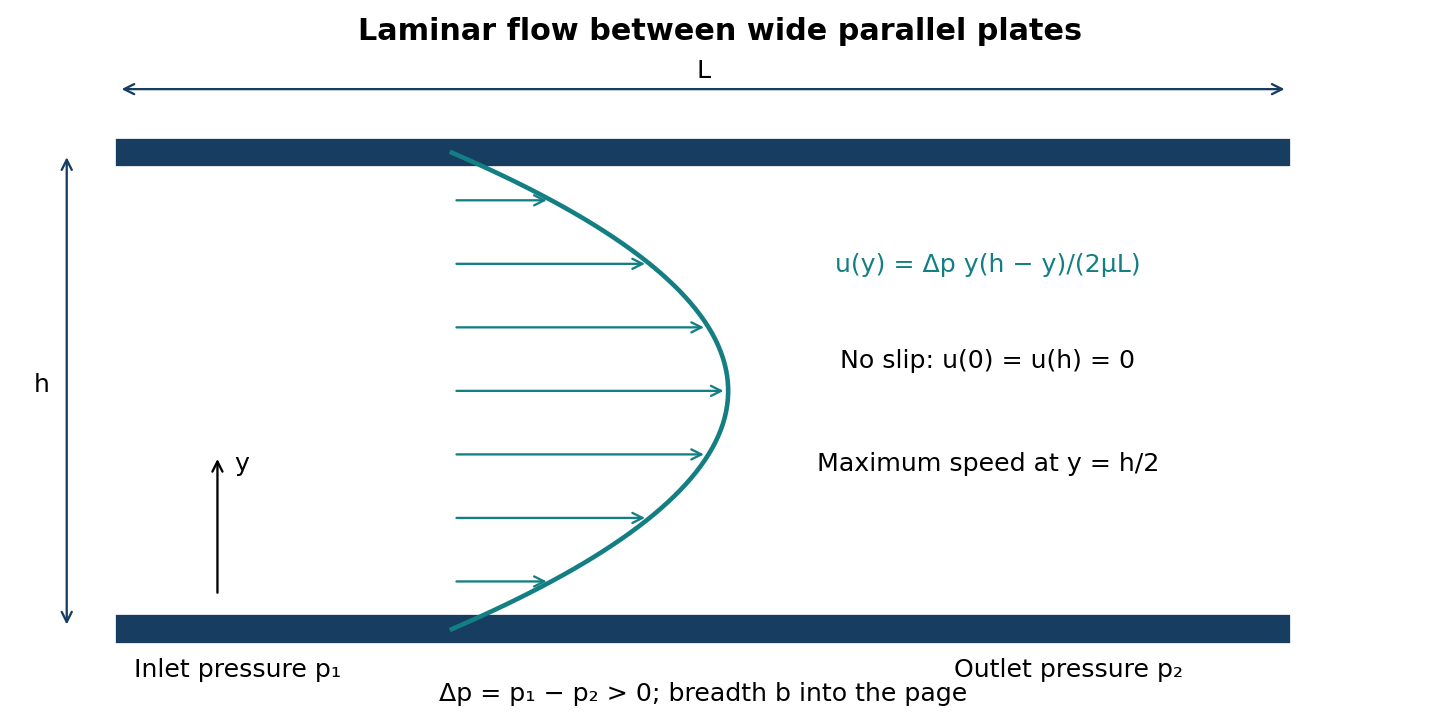
Assume a Newtonian incompressible fluid, constant viscosity, steady fully developed flow and plates sufficiently wide that side-edge effects are negligible. Put y = 0 on the lower plate and y = h on the upper plate. Let Δp = P = pin − pout > 0 over length L.
| Stage | Derivation |
|---|---|
| Pressure gradient | dp/dx = −Δp/L. In fully developed flow u depends only on y and the transverse velocity is zero. |
| Streamwise momentum equation | 0 = −dp/dx + μ d²u/dy² ⇒ d²u/dy² = −Δp/(μL). |
| First integration | du/dy = −Δp y/(μL) + C₁. |
| Second integration | u(y) = −Δp y²/(2μL) + C₁y + C₂. |
| No-slip at y = 0 | u(0) = 0 ⇒ C₂ = 0. |
| No-slip at y = h | u(h) = 0 ⇒ C₁ = Δp h/(2μL). |
| Velocity distribution | u(y) = Δp y(h − y)/(2μL). |
| Discharge through a strip | dQ = b u(y)dy. Therefore Q = b∫₀ʰu(y)dy. |
| Integrate | Q = Δp b/(2μL)[hy²/2 − y³/3]₀ʰ = Δp bh³/(12μL). |
| Required result | Q = Pbh³/(12μL). The mean speed is Ph²/(12μL), and centreline speed is 1.5 times the mean. |
| Wall shear for part (b) | τ = μdu/dy = Δp(h − 2y)/(2L). The maximum magnitude occurs at either wall: |τw| = Δp h/(2L). |
Question 3(b)
A concrete water tank develops a small horizontal crack 13 m below the water level. The crack elongates horizontally for a length of 3 m, through which the water leaks. The clearance between the cracks is 0.05 mm. If the wall thickness of the tank is 1.5 m, determine the: (i) rate of leakage; (ii) maximum viscous stress. Take the viscosity of water as 15 × 10³ N s/m² and the density as 1000 kg/m³.
(5 marks)
Answer
The source prints a positive exponent: μ = 15 × 10³ Pa s. Use that value literally for the calculation below. It is not a realistic ordinary-water viscosity, so the numerical leakage is conditional on the printed data.
| Step | Working / result |
|---|---|
| Pressure difference | Δp = ρgz = 1000(9.81)(13) = 127530 Pa. |
| Crack geometry | b = 3 m; h = 0.05 mm = 5 × 10⁻⁵ m; flow length L = wall thickness = 1.5 m. |
| (i) Leakage as printed | Q = Δp bh³/(12μL) = 127530(3)(5 × 10⁻⁵)³/[12(15000)(1.5)] = 1.77125 × 10⁻¹³ m³/s. |
| (ii) Maximum viscous stress | |τmax| = Δp h/(2L) = 127530(5 × 10⁻⁵)/(2 × 1.5) = 2.1255 Pa. |
| Dependence on viscosity | Q = 2.656875 × 10⁻⁹/μ m³/s when μ is in Pa s. Wall shear for the given pressure gradient does not depend on μ. |
A corrected numerical leakage requires clarification of the intended viscosity. Changing the exponent or inserting a decimal point without stating it would solve a different question.
Question 4(a)
Define the following terms as applied in thermodynamics: (i) surrounding; (ii) boundary; (iii) system.
(3 marks)
Answer
| Term | Definition |
|---|---|
| Surroundings | Everything external to the selected system that may interact with it. |
| Boundary | The real or imaginary surface separating a system from its surroundings; it may be fixed or moving. |
| System | The specified quantity of matter or region of space chosen for thermodynamic study. |
Question 4(b)
Steam at a pressure of 20 bar and a temperature of 250°C is expanded isentropically to a pressure of 3 bar. It is further expanded hyperbolically to a pressure of 1.2 bar. Determine: (i) the final conditions of the steam; (ii) change of entropy during the hyperbolic process.
(5 marks)
Answer
Take all pressures as absolute and use steam properties from IAPWS-IF97. Hyperbolic expansion means pv = constant. For real steam it does not generally mean constant temperature.
| Stage | Working / result |
|---|---|
| Initial superheated state | At 20 bar, 250°C: s₁ = 6.547418 kJ/(kg K). |
| Isentropic expansion to 3 bar | s₂ = s₁. At 3 bar: sf = 1.671765, sg = 6.991566 kJ/(kg K); vf = 0.00107318, vg = 0.60578549 m³/kg. |
| Intermediate quality and volume | x₂ = (s₂ − sf)/(sg − sf) = 0.916510; v₂ = vf + x₂(vg − vf) = 0.55529833 m³/kg. |
| Hyperbolic final volume | p₂v₂ = p₃v₃ ⇒ v₃ = (3/1.2)(0.55529833) = 1.38824582 m³/kg. |
| Properties at 1.2 bar | Tsat = 104.7838°C; vf = 0.00104727, vg = 1.42844549 m³/kg; sf = 1.360753, sg = 7.297633 kJ/(kg K). |
| (i) Final condition | x₃ = (v₃ − vf)/(vg − vf) = 0.971837. Thus the final state is wet saturated steam at 1.2 bar and 104.784°C, with dryness fraction 0.971837 (97.184%). |
| Final specific entropy | s₃ = sf + x₃(sg − sf) = 7.130433 kJ/(kg K). |
| (ii) Specific entropy change | Δs₂₃ = s₃ − s₂ = +0.583015 kJ/(kg K). A total entropy change would require the mass. |
Question 4(c)
A single wheel impulse turbine of blade wheel diameter 1.2 m discharges 650 kg of steam per hour to the plane of the wheel. If the blade angles at inlet and outlet are 45° and 40° respectively, and the blade wheel rotates at 2800 rpm, if there is a 15% loss of relative velocity due to friction in the blade when the absolute velocity at exit is radial, determine: (i) nozzle angle; (ii) velocity of steam at entry; (iii) the power developed by the turbine; (iv) the diagram efficiency.
(12 marks)
Answer
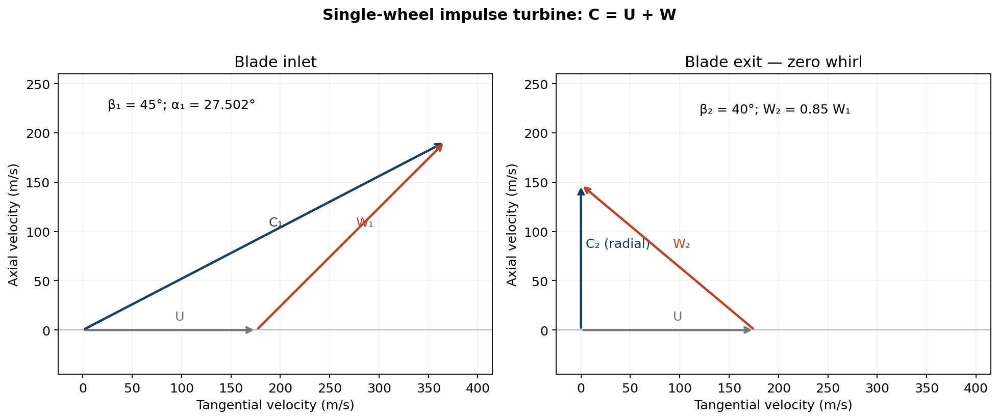
| Step | Working / result |
|---|---|
| Blade speed and flow | U = πDN/60 = π(1.2)(2800)/60 = 175.9292 m/s; ṁ = 650/3600 = 0.1805556 kg/s. |
| Exit triangle | Radial absolute exit means Cw₂ = 0. Therefore W₂cos40° = U ⇒ W₂ = 229.6592 m/s. |
| Relative inlet speed | W₂ = 0.85W₁ ⇒ W₁ = 270.1873 m/s. |
| Inlet absolute components | Cw₁ = U + W₁cos45° = 366.9805 m/s; Cf₁ = W₁sin45° = 191.0513 m/s. |
| (i) Nozzle angle | α₁ = tan⁻¹(Cf₁/Cw₁) = 27.5016° to the tangent. |
| (ii) Entry velocity | C₁ = √(Cw₁² + Cf₁²) = 413.7333 m/s. |
| (iii) Diagram power | P = ṁU(Cw₁ − Cw₂)/1000 = 11.6571 kW. |
| (iv) Diagram efficiency | ηd = U(Cw₁ − Cw₂)/(C₁²/2) = 0.754345 = 75.4345%. |
Question 5(a)
Wet steam at 20 bar is carried in steel steam mains of 140 mm diameter, thickness 6 mm and length 8 m. The mains are insulated with an inner layer of diatomaceous earth 38 mm thick and an outer layer of magnesia 30 mm thick. The inside heat transfer coefficient is 8.5 W/(m² K). The thermal conductivities of the diatomaceous earth, magnesia and steel are 0.09 W/(m K), 0.06 W/(m K) and 48 W/(m K) respectively. Determine: (i) rate of heat loss; (ii) temperature of the outside surface of the lagging. Take outside temperature as 20°C.
(10 marks)
Answer
As printed, this question does not supply the outside heat-transfer coefficient or an equivalent outside surface boundary condition. Both requested numerical values therefore cannot be uniquely determined. The complete resistance solution below shows the missing quantity explicitly. Assume that 140 mm is the internal diameter and that 20 bar is absolute.
| Resistance / quantity | Working / result |
|---|---|
| Steam temperature | Wet steam is saturated: Ts = 212.3845°C at 20 bar. |
| Radii | r₁ = 0.070 m, r₂ = 0.076 m, r₃ = 0.114 m, r₄ = 0.144 m; length L = 8 m. |
| Inside film | Ri = 1/(hi2πr₁L) = 0.03343591 K/W. |
| Steel | Rs = ln(r₂/r₁)/(2πksL) = 0.000034085 K/W. |
| Diatomaceous earth | Rd = ln(r₃/r₂)/(2πkdL) = 0.08962747 K/W. |
| Magnesia | Rm = ln(r₄/r₃)/(2πkmL) = 0.07746033 K/W. |
| Unknown outside film | Ro = 1/(ho2πr₄L) = 1/[ho2π(0.144)(8)]. |
| (i) Heat-loss function | q = (212.3845 − 20)/(Ri + Rs + Rd + Rm + Ro) = 192.3845/(0.20055779 + Ro) W. |
| (ii) Outside lagging surface | Tsurface = 20 + qRo °C. |
| Additional condition, explicitly conditional | Heat loss | Outside surface |
|---|---|---|
| If ho is additionally specified as 8.5 W/(m² K), while retaining the stated inside hi | 887.336 W | 34.4224°C |
| If “inside” was intended to read “outside”, with negligible inside film resistance | 1049.129 W | 37.0521°C |
Neither added condition is stated in the source. They illustrate the consequences of possible clarifications; they must not be presented as a unique answer to the printed problem.
Question 5(b)
The ultimate analysis of a sample of fuel was carbon 85.5% and hydrogen 14.5%. The analysis of the dry products gave 14% CO₂ “and some and some O₂” [wording as printed]. Calculate the: (i) A/F ratio supplied to the engine; (ii) mixture strength. Take atomic masses as C = 12, H = 1, O = 16.
(10 marks)
Answer
Assume complete combustion, no CO or unburned fuel, and dry air containing 21% O₂ and 79% N₂ by volume. Interpret the unlisted dry products as excess oxygen and nitrogen. Use a basis of 1 kg fuel and measure gas amounts in kmol.
| Step | Working / result |
|---|---|
| Carbon products | nCO₂ = 0.855/12 = 0.07125 kmol. |
| Hydrogen products | nH₂O = 0.145/2 = 0.07250 kmol; exclude water from the dry-gas total. |
| Stoichiometric oxygen | nO₂,st = 0.855/12 + 0.145/4 = 0.10750 kmol. |
| Dry gas amount | nDry = nCO₂/0.14 = 0.508928571 kmol. |
| Actual oxygen supplied a | Dry products: 0.07125 CO₂ + (a − 0.1075) O₂ + (79/21)a N₂. Thus 0.508928571 = 0.07125 + a − 0.1075 + (79/21)a. |
| Solve for a | a = 0.1144875 kmol O₂; nitrogen = 0.430691071 kmol; excess oxygen = 0.0069875 kmol. |
| (i) Actual air/fuel ratio | A/F = 32a + 28(79/21)a = 15.72295 kg air/kg fuel. |
| Stoichiometric air/fuel ratio | (A/F)st = 0.1075[32 + 28(79/21)] = 14.76333 kg/kg. |
| (ii) Mixture strength / equivalence ratio | φ = (F/A)actual/(F/A)st = (A/F)st/(A/F)actual = 0.938967, or 93.8967% of stoichiometric fuel strength. |
| Mixture classification | φ < 1: lean mixture. Air ratio λ = 1/φ = 1.065, corresponding to 6.5% excess air. |
Question 6(a)
1 m³ of air is heated reversibly at constant pressure from 25°C to 400°C, and then cooled reversibly at constant volume back to the initial temperature. The initial pressure is 1.03 bar. Determine the: (i) net heat flow; (ii) overall change of entropy.
(6 marks)
Answer
Treat air as an ideal gas with constant R = 0.287, Cp = 1.005 and Cv = 0.718 kJ/(kg K). Temperatures are absolute in entropy expressions; positive heat denotes heat entering the air.
| Step | Working / result |
|---|---|
| Temperatures and mass | T₁ = T₃ = 298.15 K; T₂ = 673.15 K; m = p₁V₁/(RT₁) = 103(1)/(0.287 × 298.15) = 1.203706 kg. |
| Constant-pressure heating | Q₁₂ = mCp(T₂ − T₁) = +453.6468 kJ. |
| Constant-volume cooling | Q₂₃ = mCv(T₁ − T₂) = −324.0979 kJ. |
| (i) Net heat | Qnet = Q₁₂ + Q₂₃ = +129.5489 kJ, supplied to the air. |
| Entropy of first process | ΔS₁₂ = mCp ln(T₂/T₁). |
| Entropy of second process | ΔS₂₃ = mCv ln(T₁/T₂). |
| (ii) Overall entropy change | ΔS = m(Cp − Cv)ln(T₂/T₁) = mRln(673.15/298.15) = +0.281336 kJ/K. |
| Final-state check | V₃ = V₂ = 2.257756 m³ and p₃ = 45.6205 kPa. Returning to the original temperature does not return the air to its original state. |
Question 6(b)
In a power generating gas turbine unit, a high pressure turbine stage drives the compressor while a low pressure turbine drives the alternator. The overall pressure ratio is 6:1, and the maximum temperature is 700°C. The isentropic efficiencies of the compressor, high pressure turbine and low pressure turbine are 0.8, 0.83 and 0.85 respectively. The mechanical efficiencies of both shafts are 95%. Taking the intake air conditions as 1.01 bar and 20°C, calculate: (i) the pressure between turbine stages; (ii) the thermal efficiency; (iii) the shaft power when the mass flow rate is 60 kg/s. For air γ = 1.4 and Cp = 1.005 kJ/(kg K); gases γ = 1.33 and Cp = 1.14 kJ/(kg K).
(14 marks)
Answer
Neglect fuel mass, intake/exhaust and combustor pressure losses, and heat loss. There is no reheat. The H.P. turbine must supply compressor work after its shaft mechanical loss. Use the usual examination convention qin = Cpg(T₃ − T₂) for the combustor heat input.
| Stage | Working / result |
|---|---|
| Compressor inlet and turbine inlet | T₁ = 293.15 K; p₁ = 1.01 bar; p₂ = p₃ = 6.06 bar; T₃ = 973.15 K. |
| Compressor exit | T₂s = T₁6^((1.4−1)/1.4); T₂ = T₁ + (T₂s − T₁)/0.8 = 538.1173 K. |
| Compressor work | wc = Cpa(T₂ − T₁) = 246.1921 kJ/kg. |
| H.P. shaft balance | 0.95 Cpg(T₃ − T₄) = wc ⇒ T₄ = 745.8258 K. |
| H.P. isentropic exit | ηH = (T₃ − T₄)/(T₃ − T₄s) ⇒ T₄s = 699.2654 K. |
| (i) Interstage pressure | p₄ = p₃(T₄s/T₃)^(γg/(γg−1)) = 6.06(699.2654/973.15)^(1.33/0.33) = 1.599455 bar absolute. |
| L.P. isentropic exit | T₅s = T₄(p₅/p₄)^((γg−1)/γg), with p₅ = 1.01 bar ⇒ T₅s = 665.4264 K. |
| Actual L.P. exit | T₅ = T₄ − 0.85(T₄ − T₅s) = 677.4863 K. |
| Useful L.P. shaft work | wshaft = 0.95(1.14)(T₄ − T₅) = 74.01166 kJ/kg. |
| Heat supplied | qin = 1.14(973.15 − 538.1173) = 495.9373 kJ/kg. |
| (ii) Thermal efficiency | ηth = wshaft/qin = 0.1492359 = 14.9236%. |
| (iii) Output shaft power | Pshaft = 60 × 74.01166 = 4440.700 kW = 4.44070 MW. |
The H.P. turbine work has already been used to balance the compressor. Do not subtract compressor work a second time from the L.P. shaft output. Alternator electrical efficiency is not specified, so the final power is mechanical shaft power.
Question 7(a)
In an ideal constant pressure cycle, the overall volume ratio of the cycle is 9:1. The volume ratio of the adiabatic compression is 6:1. The pressure, volume and temperature of the air at the beginning of the adiabatic compression are 150 kN/m², 0.095 m³ and 25°C respectively. Taking γ = 1.4 and Cp = 1.005 kJ/(kg K), determine the thermal efficiency of the cycle.
(9 marks)
Answer
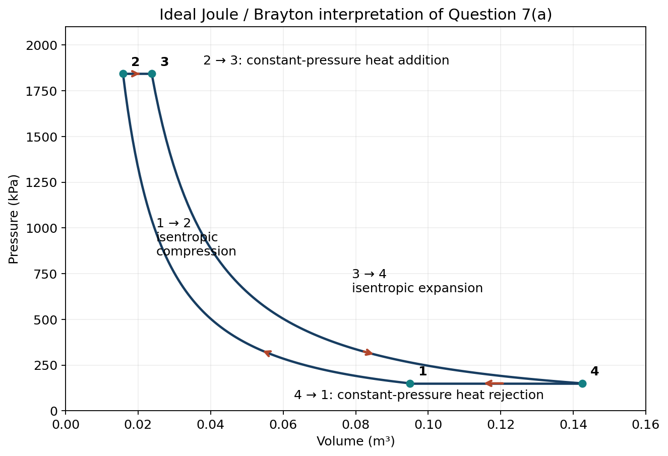
Interpret “constant pressure cycle” as the ideal Joule/Brayton cycle: two isentropic processes connected by constant-pressure heating and cooling. This interpretation accommodates both stated volume ratios. Define the overall volume ratio as Vmax/Vmin = V₄/V₂ = 9 and compression volume ratio as V₁/V₂ = 6.
| Step | Working / result |
|---|---|
| Volumes | V₁ = 0.095 m³; V₂ = V₁/6 = 0.0158333 m³; V₄ = 9V₂ = 0.1425 m³. Equal isentropic pressure ratios give V₄/V₃ = 6, hence V₃ = 0.02375 m³. |
| Compression | T₂/T₁ = (V₁/V₂)^(γ−1) = 6^0.4 ⇒ T₂ = 610.5136 K. |
| Constant-pressure heating | T₃/T₂ = V₃/V₂ = 1.5 ⇒ T₃ = 915.7703 K. |
| Constant-pressure cooling | T₄/T₁ = V₄/V₁ = 1.5 ⇒ T₄ = 447.2250 K. |
| Heat input | qin = Cp(T₃ − T₂) = 306.7831 kJ/kg. |
| Heat rejected | qout = Cp(T₄ − T₁) = 149.8204 kJ/kg. |
| Thermal efficiency | η = 1 − qout/qin = 1 − 6^−0.4 = 0.5116407 = 51.1641%. |
The initial pressure and volume do not affect the efficiency ratio. If a Diesel cycle was intended, the stated “overall” and compression volume ratios need clarification: the maximum/minimum volume ratio of an ordinary Diesel cycle equals its compression ratio.
Question 7(b)
A three-stage, single acting reciprocating air compressor has a low pressure cylinder of 450 mm diameter and 300 mm stroke. The clearance volume of the low pressure cylinder is 5% of the swept volume. The intake air conditions are 1 bar and 18°C while the final delivery pressure is 15 bar. Intermediate pressures are ideal and intercooling is complete. The compression and expansion index is 1.3 throughout. Calculate: (i) intermediate pressures; (ii) effective swept volume of the low pressure cylinder; (iii) work done per kg of air.
(11 marks)
Answer
Use absolute pressures, complete intercooling to 291.15 K, negligible intercooler pressure drop and equal pressure ratios for minimum work. Let C = Vclearance/Vs = 0.05 and use Rair = 0.287 kJ/(kg K).
| Step | Working / result |
|---|---|
| Equal stage pressure ratio | r = (15/1)^(1/3) = 2.466212. |
| (i) Intermediate pressures | p₂ = p₁r = 2.466212 bar; p₃ = p₁r² = 6.082202 bar. The final stage delivers at 15 bar. |
| L.P. swept volume | Vs = πD²L/4 = π(0.45)²(0.30)/4 = 0.04771294 m³ per cycle. |
| Volumetric efficiency with clearance | ηv = 1 + C − C r^(1/n) = 1.05 − 0.05(2.466212)^(1/1.3) = 0.9498775. |
| (ii) Effective swept / fresh intake volume | Veff = ηvVs = 0.04532144 m³ per cycle = 45.3214 litres per cycle, measured at intake conditions. |
| Work of one stage | wstage = [n/(n − 1)]RT₁[r^((n−1)/n) − 1]. |
| (iii) Total work for three stages | w = 3[1.3/0.3](0.287)(291.15)[2.466212^(0.3/1.3) − 1] = 251.5791 kJ/kg. |
Clearance reduces the amount of fresh air admitted per cycle. Under the ideal polytropic re-expansion assumptions used here it does not change the indicated work per kilogram of delivered air.