Plant Control Systems and Automation — June/July 2024
KNEC Diploma in Mechanical Engineering — Module III. Paper code: 2502/302. Time: 3 hours.
These independent revision answers are not official KNEC marking schemes. Attempt each question before reading its answer. All optional questions are included for study.
Plant option. Answer any FIVE out of EIGHT questions. Each whole question carries 20 marks. The supplied 8051 instruction-set appendix is used where relevant; all eight questions are answered here.
All six original figures and four printed tables are retained. Worked answers use the actual summing signs, an unloaded RC output, the printed 12 μF capacitor and classic 8051 timing assumptions.
Question 1(a)
State four advantages of closed-loop over open-loop control systems.
(4 marks)
Answer
- Corrects deviations automatically using measured output feedback.
- Reduces the effect of disturbances within the effective loop bandwidth.
- Makes the overall response less sensitive to many plant-parameter variations.
- Can improve steady-state accuracy and tracking when the controller is properly designed.
Feedback does not guarantee stability or accuracy by itself; the sign, dynamics and sensor quality matter.
Question 1(b)
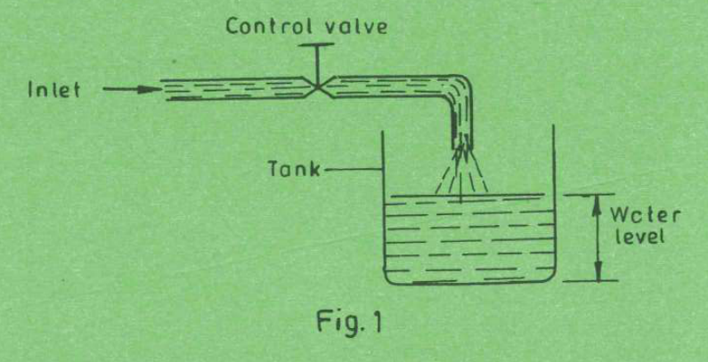
Figure 1 shows a water tank level control system. State: (i) reference variable; (ii) controlled variable; (iii) actuator; (iv) type of control.
(4 marks)
Answer
| Item | Answer |
|---|---|
| Reference variable | The desired water level (set point). It is a desired value, although a separate reference-setting element is not drawn. |
| Controlled variable | The actual water level in the tank. |
| Actuator / final control element | The inlet control valve adjusts water inflow; its handle or valve-operating mechanism supplies the actuation. |
| Type of control as drawn | Manual/open-loop valve adjustment: no automatic level sensor or feedback linkage is shown. If a person observes the level and readjusts the valve, that person closes a manual feedback loop; an automatic float loop must not be assumed from this sketch. |
Question 1(c)
Explain each of the following signals with respect to feedback control systems: (i) feedback signal; (ii) error signal; (iii) disturbance signal.
(6 marks)
Answer
| Signal | Explanation |
|---|---|
| Feedback | A signal derived from the measured output and returned to the comparator, often after sensor scaling H(s). |
| Error | The difference between reference and measured feedback; for negative feedback, E(s) = R(s) − H(s)C(s). |
| Disturbance | An unwanted input that changes the process output independently of the commanded reference, for example a load change or change in inlet temperature. |
Question 1(d)
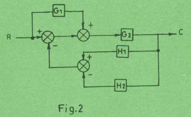
Figure 2 shows a block diagram of a control system. Determine the transfer function C/R.
(6 marks)
Answer
| Step | Working |
|---|---|
| Lower summing point | Feedback B = H₁C − H₂C = (H₁ − H₂)C, using the printed + and − signs. |
| First summing point | E = R − B = R − (H₁ − H₂)C. |
| Second summing point | Its two forward inputs add: V = E + G₁R = (1 + G₁)R − (H₁ − H₂)C. |
| Output equation | C = G₂V = G₂(1 + G₁)R − G₂(H₁ − H₂)C. |
| Required transfer function | C/R = G₂(1 + G₁)/[1 + G₂(H₁ − H₂)]. |
The upper G₁ branch originates at the reference input before the first comparator; it is feedforward, not an additional series block in the main feedback loop.
Question 2(a)
State four merits of automated plant control systems.
(4 marks)
Answer
- Improved consistency of product quality through repeatable process conditions.
- Higher throughput and efficient continuous operation.
- Reduced routine manual labour and exposure to hazardous process areas.
- Better use of energy and raw materials through coordinated monitoring and control.
Question 2(b)
(i) Define “forward path gain” with reference to a control system. (ii) A control system consists of forward path element G(s) and negative unity feedback. (I) Draw its block diagram; (II) write its transfer function.
(6 marks)
Answer
(i) Forward path gain is the product of the transfer gains along a directed input-to-output path, without traversing any node more than once. For a single series forward chain it is the product of the gains of all its blocks.
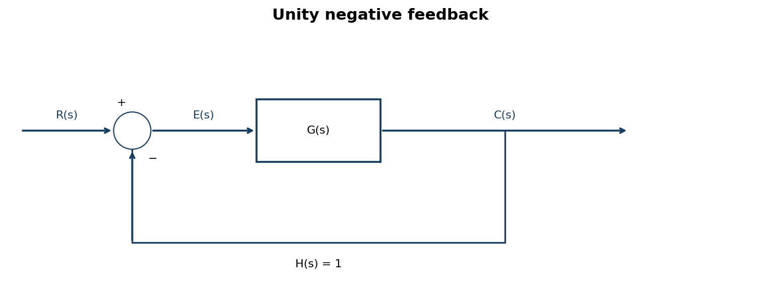
(ii) E = R − C and C = GE, so C = G(R − C). Hence the closed-loop transfer function is C(s)/R(s) = G(s)/[1 + G(s)].
Question 2(c)
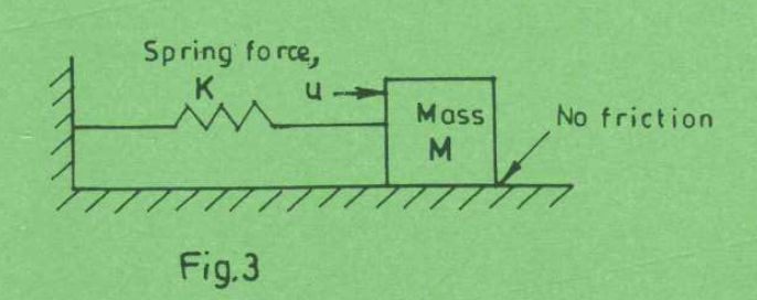
Figure 3 shows a mechanical translation system. (i) Write its differential equation; (ii) determine its transfer function.
(6 marks)
Answer
Let x(t) be mass displacement to the right from the spring’s equilibrium position and u(t) the applied force. The surface is frictionless; K is spring stiffness and M is mass.
| Step | Working |
|---|---|
| (i) Newton’s second law | u(t) − Kx(t) = M d²x/dt², or Mẍ + Kx = u. |
| Laplace transform | (Ms² + K)X(s) = U(s), with zero initial displacement and velocity. |
| (ii) Transfer function | X(s)/U(s) = 1/(Ms² + K). |
| Physical check | Natural frequency ωn = √(K/M). No damping term is added because the figure states no friction. |
Question 2(d)
Draw a labelled block diagram showing the basic components of a closed-loop control system.
(4 marks)
Answer
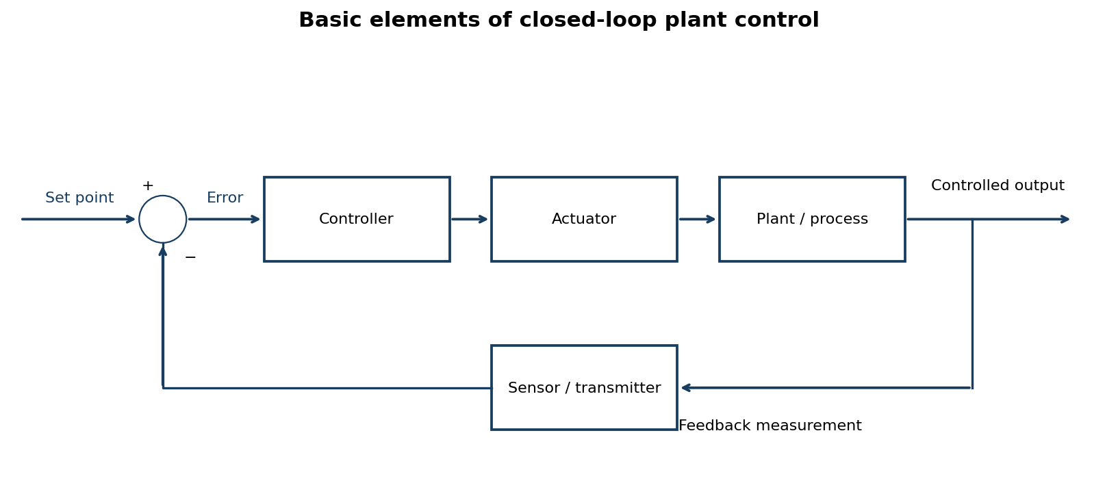
The controlled output is measured and compared with the reference. The controller changes the manipulated input through the actuator to reduce the error.
Question 3(a)
Table 1 shows elements of an electrical network and corresponding mechanical rotational elements. Complete the table.
| Electrical elements | Mechanical rotational elements |
|---|---|
| Current | — |
| — | Inertia |
| Resistance | — |
(3 marks)
Answer
Use the torque–voltage (impedance) analogy: voltage corresponds to torque and current corresponds to angular velocity.
| Electrical element / quantity | Mechanical rotational equivalent |
|---|---|
| Current i | Angular velocity ω |
| Inductance L | Moment of inertia J |
| Resistance R | Viscous rotational friction / damping coefficient B |
For example, voltage across an inductor is L di/dt, corresponding to inertial torque J dω/dt; resistor voltage Ri corresponds to damping torque Bω.
Question 3(b)
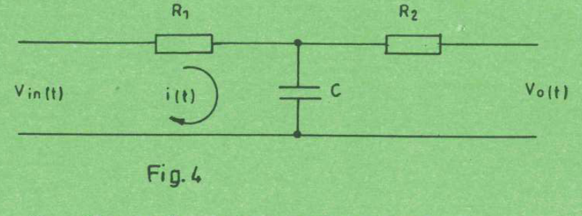
Figure 4 shows an RC network. (i) Write the differential equations that describe the system; (ii) determine its transfer function.
(6 marks)
Answer
Assume the output is measured by an ideal high-impedance instrument, as no output load is drawn. Therefore no current flows through R₂, its voltage drop is zero and vo = vC.
| Step | Working |
|---|---|
| (i) Capacitor equation | i(t) = C dvC/dt. |
| Input loop equation | vin(t) = R₁i(t) + vC(t). |
| Output equation | vo(t) = vC(t), because iR₂ = 0. |
| Combined differential equation | R₁C dvo/dt + vo = vin. |
| (ii) Transfer function | Vo(s)/Vin(s) = 1/(1 + sR₁C), for zero initial capacitor voltage. |
R₂ affects the transfer only if a load draws output current. For a stated load RL, Vo/Vin = RL/[R₁ + R₂ + RL + sR₁C(R₂ + RL)]. No such RL is supplied in the printed circuit.
Question 3(c)
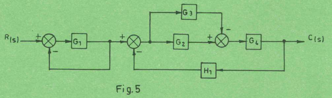
Figure 5 shows a block diagram representation of a control system. (i) Reduce it to its canonical form; (ii) determine the transfer function C(s)/R(s).
(8 marks)
Answer
| Reduction | Result |
|---|---|
| Local negative unity loop around G₁ | K₁ = G₁/(1 + G₁). Its output is independent of the later H₁ loop. |
| Parallel middle paths | The upper G₃ contribution is subtracted at the third summing point: parallel result = G₂ − G₃. |
| Right forward path | K₂ = (G₂ − G₃)G₄. |
| Right negative-feedback loop | Transfer from its reference to output = K₂/(1 + K₂H₁). |
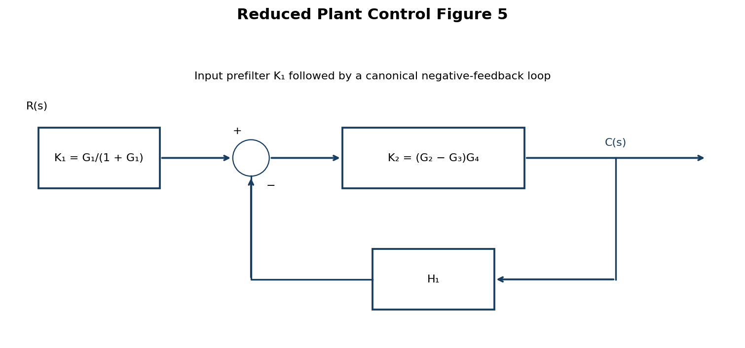
(i) If a single comparator at the overall input is required, an equivalent canonical form has F = K₁K₂ and H = H₁/K₁ (where K₁ ≠ 0), giving F/(1 + FH).
(ii) C/R = K₁K₂/(1 + K₂H₁) = G₁(G₂ − G₃)G₄ / {(1 + G₁)[1 + (G₂ − G₃)G₄H₁]}. The unreduced expression also covers cases where the canonical H₁/K₁ rewriting is undefined.
Question 3(d)
Explain the effect of feedback element in a control system.
(3 marks)
Answer
The feedback element measures and scales the output so it can be compared with the reference. Its transfer H(s) enters the closed-loop denominator 1 + G(s)H(s), altering accuracy, sensitivity, bandwidth and stability. Correct negative feedback can reduce disturbances and gain variation, but sensor error is also returned to the loop and excessive phase lag can destabilise it.
Question 4(a)
State four areas of application of stepper motors.
(4 marks)
Answer
- Positioning axes in printers and plotters.
- CNC machine-tool feed positioning.
- Robotic or laboratory positioning stages.
- Metering pumps and controlled valve-positioning mechanisms.
Question 4(b)
(i) Define step angle with respect to stepper motors. (ii) A stepper motor makes 200 steps per revolution. It moves 1140 steps counterclockwise and 2170 steps clockwise. Determine: (I) step angle; (II) final position of the motor.
(8 marks)
Answer
(i) Step angle is the angular displacement of the rotor for one commanded step of the specified drive mode.
| Step | Working / result |
|---|---|
| (I) Step angle | α = 360°/200 = 1.8° per step. |
| Counterclockwise movement | 1140 × 1.8° = 2052° counterclockwise. |
| Clockwise movement | 2170 × 1.8° = 3906° clockwise. |
| Net movement | 2170 − 1140 = 1030 steps clockwise = 1854° clockwise. |
| (II) Final angular position | 1854° = 5 × 360° + 54°. Thus the rotor is 54° clockwise from its initial position, equivalent to 306° counterclockwise. |
This assumes every commanded step is completed and the same step mode is used throughout.
Question 4(c)
Draw a labelled torque-speed characteristic curve of a.c. servo motor.
(4 marks)
Answer
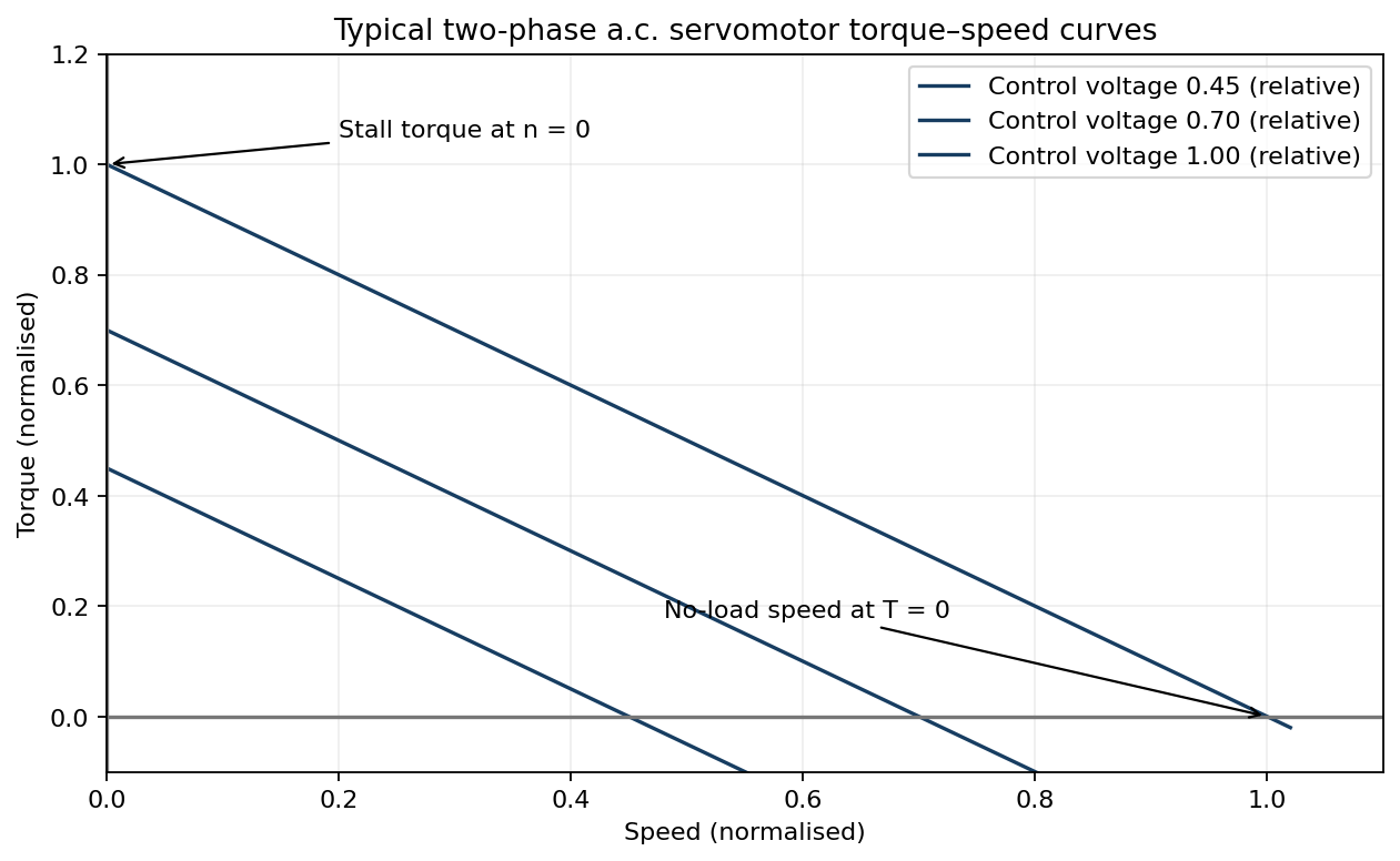
At fixed control voltage, available torque decreases as speed rises. Stall torque occurs at zero speed; no-load speed occurs where developed torque falls to the no-load requirement. Increasing control-voltage magnitude increases available torque, while reversing its phase reverses the torque direction.
Question 4(d)
Draw symbolic diagram representation of the following pneumatic valves: (i) 4/3; (ii) 4/2.
(4 marks)
Answer
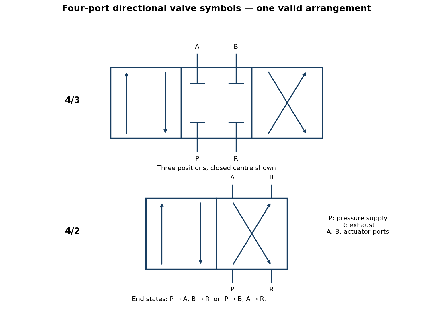
Ports are P (pressure supply), R (exhaust), A and B (actuator). The end states connect P → A and B → R, or P → B and A → R. A 4/3 valve has a third central state; the drawing blocks all four ports in that state.
Question 5(a)
Explain the following with respect to process control: (i) safety; (ii) quality; (iii) economics.
(6 marks)
Answer
| Objective | Explanation |
|---|---|
| Safety | Keep pressure, temperature, level and other variables within safe limits; detect abnormal states and initiate alarms, interlocks or shutdowns before harm occurs. |
| Quality | Maintain process conditions within specified tolerances so the product has consistent composition, dimensions or other required properties. |
| Economics | Use energy, labour and materials efficiently, reduce off-specification waste and downtime, and maintain an economical production rate. |
Question 5(b)
Draw a labelled time response curve of a closed-loop second order control system.
(4 marks)
Answer
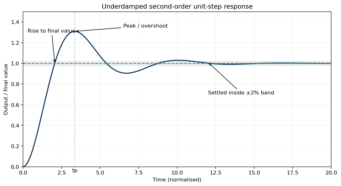
Rise time tr measures the initial rise, commonly from 10% to 90% of final value; peak time tp is the time of the first maximum; percentage overshoot is 100(ypeak − yfinal)/yfinal; settling time ts is the time after which the response remains inside the specified band, here ±2%. For the standard denominator s² + 2ζωn s + ωn², 0 < ζ < 1 gives this oscillatory response.
Question 5(c)
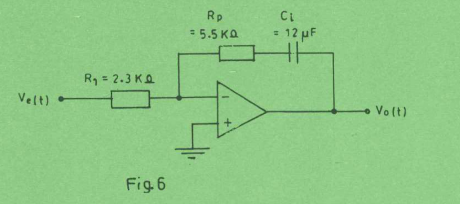
Figure 6 shows an operational-amplifier-based proportional plus integral controller. Determine: (i) proportional gain Kp; (ii) integral gain Ki; (iii) expression for output voltage Vo(t).
(6 marks)
Answer
The printed capacitor is 12 μF, not 12 mF. Let R₁ = 2.3 kΩ and Rp = 5.5 kΩ. Assume an ideal op-amp and zero initial capacitor charge. The feedback impedance is Rp + 1/(sCi).
| Quantity | Working / result |
|---|---|
| Circuit transfer | Vo/Ve = −[Rp + 1/(sCi)]/R₁ = −(Kp + Ki/s). |
| (i) Proportional gain magnitude | Kp = Rp/R₁ = 5500/2300 = 2.391304. |
| (ii) Integral gain magnitude | Ki = 1/(R₁Ci) = 1/[2300(12 × 10⁻⁶)] = 36.231884 s⁻¹. |
| Integral time | Ti = Kp/Ki = RpCi = 0.0660 s. |
| (iii) Output voltage | vo(t) = −2.391304 ve(t) − 36.231884 ∫₀ᵗ ve(τ)dτ. |
The minus signs follow from the inverting op-amp configuration. A nonzero initial integral state would add the corresponding initial output term.
Question 5(d)
Differentiate between: (i) dead time and lag time; (ii) error and dead band, with respect to analogue controllers.
(4 marks)
Answer
| Terms | Difference |
|---|---|
| Dead time / lag time | Dead time is a delay after an input change during which no output response begins. Lag is a gradual dynamic response after the change reaches the system; a first-order lag responds immediately but approaches its new value over a time constant. |
| Error / dead band | Error is the instantaneous difference between reference and measured feedback. Dead band is a finite input/error range within which the controller or element produces no change in output. |
Question 6(a)
State four merits of SCADA system.
(4 marks)
Answer
- Centralised visibility and supervision of widely distributed plant.
- Remote monitoring and authorised control reduce routine travel and response time.
- Alarm handling helps operators identify and respond to abnormal conditions.
- Historical trends and data logging support fault diagnosis, maintenance and operating decisions.
Question 6(b)
Describe the following with respect to SCADA system: (i) RTU; (ii) communication system; (iii) master station.
(6 marks)
Answer
| Part | Function |
|---|---|
| RTU — remote terminal unit | Acquires field measurements and status, performs local processing/control and exchanges data and commands with the supervisory station. |
| Communication system | Carries telemetry, alarms, status and control commands between field stations and the master, over suitable wired or wireless links and protocols. |
| Master station | Hosts supervisory software, operator displays, alarm processing, data storage and remote-control interfaces; it coordinates monitoring rather than replacing all local protective control. |
Question 6(c)
Table 2 shows a programmable logic controller instruction-list program. (i) Draw its equivalent ladder diagram; (ii) describe the control operation.
| Instruction List | Description |
|---|---|
| LD X10 | Start push button |
| OR Y10 | Motor contact |
| ANI X11 | Stop push button |
| ANI T1 | Timer contact |
| OUT Y10 | Motor starter coil |
| LD Y10 | Motor contact |
| OUT T1, K = 40 s | ON DELAY timer coil |
(10 marks)
Answer
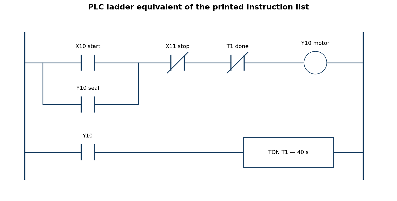
- With stop and timer-done conditions false, a momentary start X10 energises motor coil Y10.
- The Y10 contact seals in the start command after X10 is released. Y10 also energises the non-retentive on-delay timer T1.
- After 40 seconds of continuous Y10 operation, the timer-done bit becomes true. Its ANI / normally closed logical contact opens and drops Y10.
- Dropping Y10 disables and resets the timer; the seal-in contact opens. With start released, the motor remains stopped until another start command.
- Operating stop X11 while running immediately breaks the motor rung and resets the timer.
Boolean motor logic: Y10,new = (X10 OR Y10,old) AND NOT X11 AND NOT T1.done. If the start input is held on, the circuit can restart when the non-retentive timer resets; the printed program has no separate one-shot/restart lockout. Here X11 = 1 means stop requested, consistent with ANI X11. Field wiring must be mapped to that stated input meaning.
Question 7(a)
Define the following terms as used in robotics: (i) pitch; (ii) yaw; (iii) roll.
(3 marks)
Answer
| Rotation | Definition, using conventional body axes |
|---|---|
| Pitch | Rotation about the transverse / lateral y-axis, tilting the end effector up or down. |
| Yaw | Rotation about the vertical z-axis, turning it left or right. |
| Roll | Rotation about the longitudinal x-axis, twisting about its forward axis. |
Axis conventions must be declared because robot coordinate-frame definitions can differ.
Question 7(b)
Explain three features that differentiate robots from hard-wired machines.
(6 marks)
Answer
- Reprogrammability: the task sequence, positions and motions can be changed through software rather than rebuilding fixed control wiring or mechanisms.
- Flexible motion: a robot’s multiple controlled axes can perform different paths and handle different products with suitable tooling.
- Sensor integration and feedback: robots can use position, force or vision measurements to correct motion and adapt to changing work conditions.
A fixed automatic machine can also use sensors and feedback; the distinction is the robot’s combined programmable, multi-axis versatility rather than an assertion that every hard-wired machine lacks feedback.
Question 7(c)
Describe the following with respect to robots: (i) payload; (ii) repeatability; (iii) accuracy; (iv) stability.
(8 marks)
Answer
| Property | Meaning |
|---|---|
| Payload | The allowable mass and associated load moments carried at the robot interface under specified operating conditions; tooling and workpiece both contribute. |
| Repeatability | How closely the robot returns to the same commanded pose over repeated operations under the same conditions. |
| Accuracy | How closely the actual achieved pose agrees with the specified or commanded pose. |
| Stability | The ability to maintain or recover the intended operating state or pose after small disturbances without growing oscillation, loss of control or unacceptable mechanical deflection. |
Question 7(d)
List three factors considered while selecting a robot for a particular application.
(3 marks)
Answer
- Required payload, tool weight and wrist moment/inertia.
- Required reach, workspace and number of axes.
- Required accuracy, repeatability and cycle-time performance for the task.
Question 8(a)
List four special function registers in 8051 controller.
(4 marks)
Answer
- Accumulator ACC / A.
- B register.
- Program Status Word PSW.
- Stack Pointer SP.
Question 8(b)
Table 3 shows features of microcontroller families. Complete the table.
| Features of microcontroller families | 8051 | PIC | AVR |
|---|---|---|---|
| Bus width | 8-bit | — | — |
| Memory architecture | — | — | Modified Harvard architecture |
| Speed in clock / instruction cycle | — | 4 | — |
(6 marks)
Answer
Use the classic 8-bit 8051, conventional 8-bit PIC and 8-bit AVR families implied by the table. The family names alone do not define every modern derivative.
| Feature | Classic 8051 | Conventional 8-bit PIC | 8-bit AVR |
|---|---|---|---|
| Data bus width | 8-bit | 8-bit | 8-bit |
| Memory architecture | Harvard organisation: separate code and data address spaces; special instructions can read code data. | Harvard: separate program and data memories/buses. | Modified Harvard, as supplied: separate program/data paths with instructions supporting program-memory data access. |
| Basic clocks per machine / instruction cycle | 12 oscillator clocks per classic machine cycle. | 4 oscillator clocks per instruction cycle, as supplied. | Typically 1 CPU clock for a simple ALU instruction. |
Do not interpret the last row as saying every instruction takes the same time. Classic 8051 instructions take 1, 2 or 4 machine cycles; PIC branches often take extra cycles; AVR loads, branches and other instructions can require more than one clock. Faster 8051 variants and other PIC families differ.
Question 8(c)
Write an 8051 assembly language program to perform sequentially: clear the accumulator; add the decimal numbers 17 and 20 and store the result in memory location 50H; add the content of memory location 50H to accumulator and send the sum to port 1 (P1).
(6 marks)
Answer
        ORG 0000H
        CLR A           ; A = 0
        ADD A,#11H      ; add decimal 17
        ADD A,#14H      ; add decimal 20; A = 25H (37 decimal)
        MOV 50H,A       ; internal RAM[50H] = 25H
        ADD A,50H       ; A = 25H + 25H = 4AH (74 decimal)
        MOV P1,A        ; output 4AH on port 1
STOP:   SJMP STOP       ; hold here
END| Checkpoint | Value |
|---|---|
| After the first two additions | A = 37 decimal = 25H. |
| After storing | RAM location 50H = 25H and A remains 25H. |
| After ADD A,50H | A = 74 decimal = 4AH; P1 receives 4AH. |
The operands are binary encodings of decimal 17 and 20, not packed BCD. MOV 50H,A does not clear A, so the final ADD doubles the stored sum. The explicit hexadecimal immediates avoid assembler radix ambiguity.
Question 8(d)
Table 4 shows an 8051 assembly language subroutine. Determine the total: (i) byte size of the program; (ii) instruction cycles.
| Table 4 — subroutine |
|---|
| MOV A,40H |
| ADD A,R1 |
| RET |
(4 marks)
Answer
| Instruction | Opcode / bytes | Classic machine cycles |
|---|---|---|
| MOV A,40H | E5 40 — 2 bytes | 1 |
| ADD A,R1 | 29 — 1 byte | 1 |
| RET | 22 — 1 byte | 2 |
| Total | 4 bytes | 4 machine cycles |
Thus (i) program size = 4 bytes; (ii) execution = 4 classic 8051 machine cycles. At 12 oscillator clocks per machine cycle this is 48 oscillator clocks, or 48/fosc seconds. The caller’s ACALL/LCALL instruction is not included because it is not part of the printed subroutine.