Fluid Mechanics and Thermodynamics — June/July 2024
KNEC Diploma in Mechanical Engineering — Module III. Paper code: 2502/304. Time: 3 hours.
These independent revision answers are not official KNEC marking schemes. Attempt each question before reading its answer. All optional questions are included for study.
Answer FIVE questions: TWO from Section A (Questions 1–3) and THREE from Section B (Questions 4–7). Each whole question carries 20 marks.
Worked answers preserve the printed data and state pressure, friction-factor and cycle assumptions. Source ambiguities and physically inconsistent formal results are explained beside the relevant calculation.
Question 1(a)
Define the following terms as applied to reciprocating pumps: (i) co-efficient of discharge; (ii) slip.
(4 marks)
Answer
| Term | Definition |
|---|---|
| Coefficient of discharge | Cd = actual discharge/theoretical displacement discharge, for the same operating conditions. |
| Slip | Theoretical discharge minus actual discharge: slip = Qth − Qa. Percentage slip = 100(Qth − Qa)/Qth. Negative slip means actual discharge exceeds the simple displacement estimate. |
Question 1(b)
With the aid of a sketch, explain the operation of the reciprocating pump.
(6 marks)
Answer
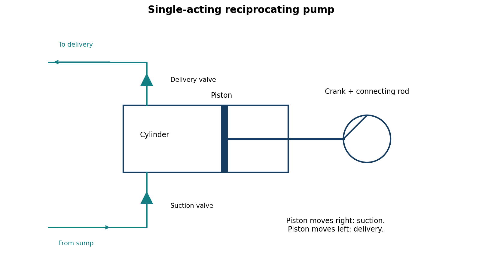
The rotating crank moves the piston back and forth. On the suction stroke, cylinder volume increases and pressure falls: the suction valve opens and the delivery valve remains closed, drawing water into the cylinder. On the return delivery stroke, cylinder volume decreases and pressure rises: the suction valve closes and the delivery valve opens to discharge water. The valves prevent reverse flow, so the reciprocating motion produces a net delivery.
Question 1(c)
A single acting reciprocating pump has a piston diameter of 300 mm and a stroke of 400 mm. The pump centre is 4.5 m above the water surface in the borehole and delivers water 25 m above. Both the suction and delivery pipes have the same diameter of 150 mm and are 8 m and 25 m long respectively. If the pump is working at 40 rpm, determine: (i) the pressure head at the beginning, middle and end of the suction stroke; (ii) the power required to drive the pump. Take density of water ρ = 1000 kg/m³.
(10 marks)
Answer
For the formal examination calculation, assume simple harmonic piston motion, negligible friction, no air vessel, negligible slip and g = 9.81 m/s². Pressure heads below are gauge heads at the pump cylinder, with the standard acceleration-head approximation.
| Quantity | Working / result |
|---|---|
| Piston / pipe areas | A = π(0.30)²/4 = 0.0706858 m²; a = π(0.15)²/4 = 0.0176715 m²; A/a = 4. |
| Crank and speed | r = stroke/2 = 0.20 m; ω = 2π(40)/60 = 4.188790 rad/s. |
| Suction acceleration head | ha = (ls/g)(A/a)rω²cosθ = 11.446908cosθ m. |
| Beginning, θ = 0° | hp = −hs − ha = −4.5 − 11.446908 = −15.946908 m gauge. |
| Middle, θ = 90° | hp = −4.5 m gauge. |
| End, θ = 180° | hp = −4.5 + 11.446908 = +6.946908 m gauge. |
| Mean ideal discharge | Q = A × stroke × N/60 = 0.01884956 m³/s. |
| If delivery surface is 25 m above pump centre | H = 4.5 + 25 = 29.5 m; ideal hydraulic power = ρgQH = 5.45497 kW. |
| If 25 m denotes height above the borehole water surface | H = 25 m; ideal hydraulic power = 4.62285 kW. |
Physical check: the calculated beginning-of-stroke gauge head is below the vacuum limit for an ordinary atmospheric suction supply. It would imply an impossible negative absolute pressure at normal atmospheric pressure, so the assumed continuous water column would separate or cavitate. The figures are formal acceleration-head results, not feasible operating pressures for this arrangement at 40 rpm. The delivery-height datum is not stated clearly, and motor input additionally requires mechanical efficiency and friction data.
Question 2(a)
(i) State two types of losses in a pipeline. (ii) Water is discharged from a reservoir into the atmosphere through a pipe of length 45 m. The entrance into the pipe is sharp and the pipe is 15 m long and 100 mm diameter. The pipe then suddenly enlarges to 225 mm diameter for the rest of its length. Taking the frictional coefficient f as 0.0048 and 0.0058 for the smaller and larger pipes respectively, determine the difference of height between the surface of the reservoir and the pipe exit which will maintain a flow of 0.0065 m³/s.
(10 marks)
Answer
(i) Major loss: wall-friction loss along a straight pipe. Minor/local losses: entrance, exit, bends, valves and changes of section.
(ii) Take the first section as 15 m and the second as 45 − 15 = 30 m. Adopt the traditional examination convention hf = 4f(L/D)V²/(2g). A sharp entrance is represented by K = 0.5. Apply Bernoulli from the reservoir surface to the free jet at the pipe exit.
| Term | Calculation | Head (m) |
|---|---|---|
| Small-pipe velocity | Q/A₁ = 0.0065/[π(0.10)²/4] | 0.827606 m/s |
| Large-pipe velocity | Q/A₂ = 0.0065/[π(0.225)²/4] | 0.163478 m/s |
| Entrance | 0.5V₁²/(2g) | 0.01745492 |
| Small-section friction | 4(0.0048)(15/0.10)V₁²/(2g) | 0.10054036 |
| Sudden enlargement | (V₁ − V₂)²/(2g) | 0.02248043 |
| Large-section friction | 4(0.0058)(30/0.225)V₂²/(2g) | 0.00421352 |
| Exit kinetic head | V₂²/(2g) | 0.00136213 |
| Required elevation difference | Sum of the above heads | 0.146051 m |
The exit kinetic head is included once; do not also add an exit loss for the same free-jet boundary. If f denotes a Darcy factor instead, omit the factor 4 in both friction terms: H = 0.067486 m. State the friction-factor convention.
Question 2(b)
Show by dimensional analysis that the equation relating the variables in the rotation of similar discs in a fluid in which the fluid motion is turbulent is given by T = ρD⁵N² φ{μ/(ND²)}. Where T = frictional torque; D = disc diameter; N = rotational speed; ρ = mass density; μ = fluid viscosity.
(10 marks)
Answer
| Step | Working |
|---|---|
| Variables and dimensions | [Ttorque] = ML²t⁻²; [D] = L; [N] = t⁻¹; [ρ] = ML⁻³; [μdynamic] = ML⁻¹t⁻¹. |
| Buckingham groups | Five variables and three fundamental dimensions give two independent dimensionless groups. Choose ρ, N and D as repeating variables. |
| Torque group | Π₁ = T/(ρN²D⁵). Both numerator and denominator have dimensions ML²t⁻². |
| Viscosity group | Π₂ = μ/(ρND²) = 1/Re. |
| Dimensionally consistent result | T = ρN²D⁵ Φ[μ/(ρND²)]. |
| Turbulent regime | The dimensionless torque coefficient depends on Reynolds number and relevant surface/geometry conditions. Dimensional analysis alone does not determine Φ. |
The printed function argument μ/(ND²) is not dimensionless if μ is dynamic viscosity: it has density units. The missing density must be included, as shown. If the symbol instead denotes kinematic viscosity ν = μdynamic/ρ, then ν/(ND²) is dimensionless and the printed form is valid with that different definition.
Question 3(a)
Show from first principles that the pressure loss due to laminar flow in a pipe is given by ΔP = 32μL V̄/D². Where μ = fluid viscosity; L = length of the pipe; V̄ = mean velocity of flow; D = pipe diameter.
(16 marks)
Answer
Assume steady, incompressible, fully developed laminar flow of a Newtonian fluid in a horizontal circular pipe, with no slip at the wall and constant viscosity. Let the radius be R = D/2 and the positive pressure drop over length L be ΔP.
| Stage | Derivation |
|---|---|
| Force balance on a cylindrical fluid core of radius r | Pressure force ΔP πr² equals resisting viscous force τ(2πrL). Therefore τ = ΔP r/(2L). |
| Newton’s viscosity law | Velocity decreases towards the wall, so τ = −μ du/dr. Hence du/dr = −ΔP r/(2μL). |
| Integrate | u(r) = −ΔP r²/(4μL) + C. |
| Wall boundary condition | u(R) = 0 ⇒ C = ΔP R²/(4μL). |
| Velocity profile | u(r) = ΔP(R² − r²)/(4μL), a parabola. |
| Integrate annular flow | Q = ∫₀ᴿ u(r)2πr dr = πΔP R⁴/(8μL) = πΔP D⁴/(128μL). |
| Mean velocity | V̄ = Q/(πD²/4) = ΔP D²/(32μL). |
| Required expression | ΔP = 32μL V̄/D². |
| Additional check | The centreline speed is twice the mean speed for this laminar profile. |
Question 3(b)
A pipe of 110 mm diameter and 120 m long conveys oil of viscosity 0.45 kg/(m s). If the pressure difference at the ends of the pipeline is 65 kN/m², calculate the quantity of oil flowing.
(4 marks)
Answer
| Step | Working |
|---|---|
| SI quantities | D = 0.110 m; L = 120 m; μ = 0.45 Pa s; ΔP = 65000 Pa. |
| Assume the laminar model in part (a) | V̄ = ΔP D²/(32μL) = 65000(0.110)²/[32(0.45)(120)] = 0.455150 m/s. |
| Discharge | Q = V̄πD²/4 = 0.00432544 m³/s = 4.32544 litres/s. |
Oil density is not supplied, so a numerical Reynolds-number check cannot be completed from the stated data alone.
Question 4(a)
A rigid vessel contains 0.8 m³ of dry saturated steam at 3.5 bar. The vessel is cooled until the pressure is reduced to 2 bar. Calculate: (i) the mass of steam in the vessel; (ii) the final dryness fraction of the steam; (iii) the amount of heat transferred during the cooling process.
(8 marks)
Answer
Treat pressures as absolute. The closed rigid vessel has constant mass and volume; boundary work is zero. Use internal energy, not enthalpy, for its heat balance.
| Step | Working / result |
|---|---|
| Initial saturated specific volume | v₁ = vg at 3.5 bar = 0.52419583 m³/kg. |
| (i) Mass | m = V/v₁ = 0.8/0.52419583 = 1.526147 kg. |
| Final specific volume | v₂ = v₁ because the vessel is rigid and sealed. |
| Saturated properties at 2 bar | vf = 0.00106052, vg = 0.88573507 m³/kg; uf = 504.4717, ug = 2529.0943 kJ/kg. |
| (ii) Dryness fraction | x₂ = (v₂ − vf)/(vg − vf) = 0.591331. |
| Internal energies | u₁ = 2548.4967; u₂ = uf + x₂(ug − uf) = 1701.6934 kJ/kg. |
| (iii) Heat transferred | Q = m(u₂ − u₁) = -1292.346 kJ. |
| Heat rejected | Approximately 1292.35 kJ leaves the vessel; the negative Q sign denotes cooling. |
Question 4(b)
Two rows of a velocity compounded impulse turbine have a mean blade speed of 150 m/s and a nozzle steam velocity of 675 m/s. The nozzle angle is 20°. The exit angles of the first moving row, fixed row and second row of moving blades are 25°, 25° and 30° respectively. There is 10% loss of velocity due to friction in all blades. The steam flow rate is 5.2 kg/s. Determine the: (i) power output; (ii) diagram efficiency.
(12 marks)
Answer
Measure nozzle and blade angles from the wheel tangent. Let C be absolute velocity, W relative velocity and U = 150 m/s blade speed. Positive whirl is in the direction of blade motion. Moving blades reduce relative speed by a factor 0.9; the fixed row reduces absolute speed by 0.9.
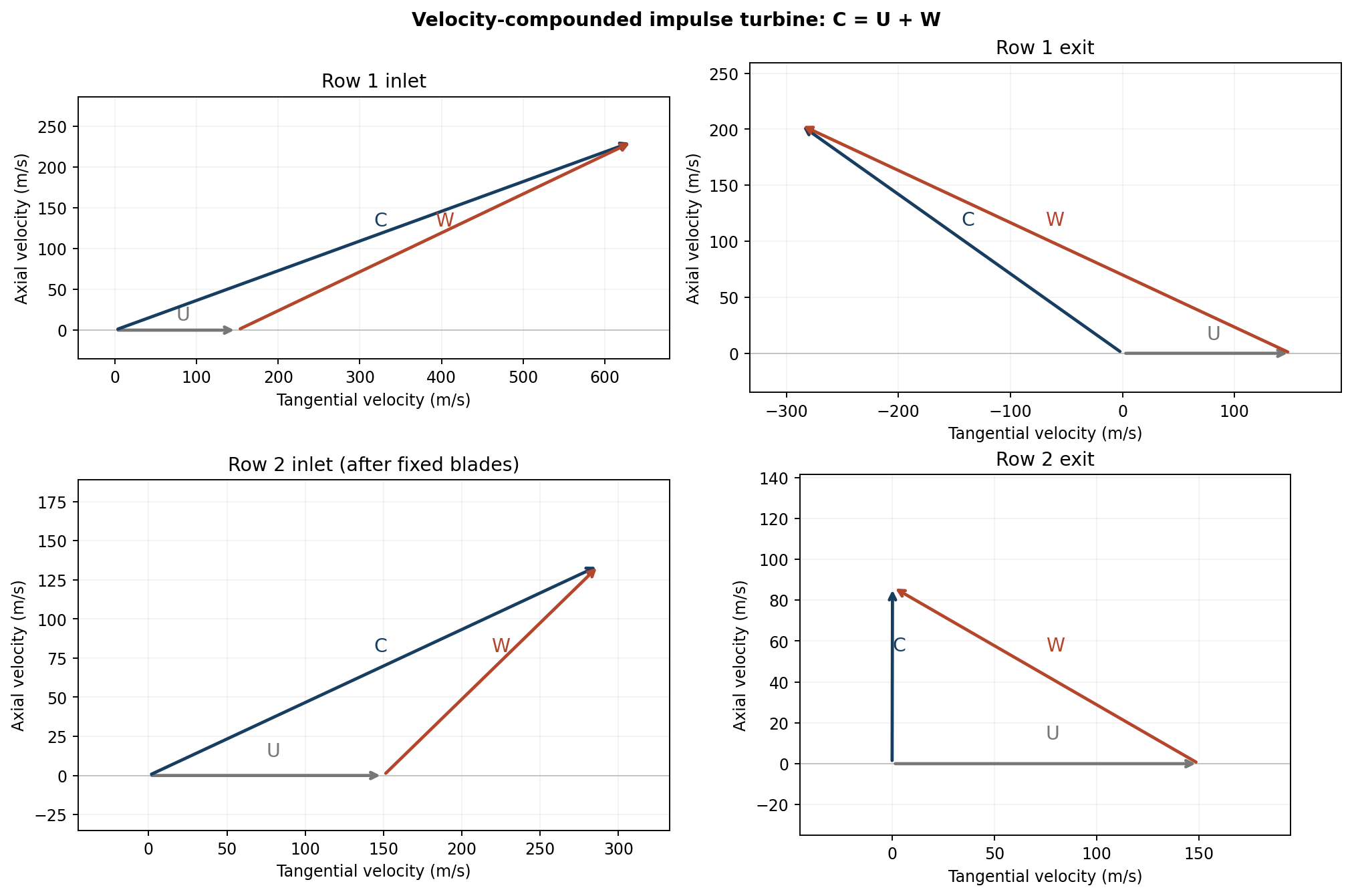
| Stage | Working | Result |
|---|---|---|
| Nozzle outlet | Cw₁ = 675cos20°; Cf₁ = 675sin20° | 634.293, 230.864 m/s |
| First-row relative inlet | W₁ = √[(Cw₁ − U)² + Cf₁²] | 536.505 m/s |
| First-row relative outlet | W₂ = 0.9W₁ | 482.854 m/s |
| First-row absolute outlet | Cw₂ = U − W₂cos25°; Cf₂ = W₂sin25° | -287.615, 204.063 m/s |
| After fixed row | C₃ = 0.9√(Cw₂² + Cf₂²) | 317.387 m/s |
| Second-row absolute inlet | Cw₃ = C₃cos25°; Cf₃ = C₃sin25° | 287.651, 134.134 m/s |
| Second-row relative inlet/outlet | W₃ = √[(Cw₃ − U)² + Cf₃²]; W₄ = 0.9W₃ | 192.197, 172.977 m/s |
| Final absolute outlet | Cw₄ = U − W₄cos30° | 0.197604 m/s |
| Specific diagram work | w = U[(Cw₁ − Cw₂) + (Cw₃ − Cw₄)]/1000 | 181.403999 kJ/kg |
| (i) Power | P = ṁw = 5.2w | 943.301 kW |
| (ii) Diagram efficiency | ηd = w/(675²/2000) | 79.629% |
Question 5(a)
A quantity of gas has an initial pressure, volume and temperature of 1.3 bar, 0.224 m³ and 21° respectively. The gas is compressed until the final volume is 0.028 m³ according to the law PV¹·³ = constant. Calculate the change in entropy. Take Cv = 0.718 kJ/(kg K), Cp = 1.005 kJ/(kg K), R = 0.287 kJ/(kg K).
(4 marks)
Answer
| Step | Working |
|---|---|
| Initial conditions | T₁ = 21 + 273.15 = 294.15 K; P₁ = 130 kPa. |
| Mass | m = P₁V₁/(RT₁) = 0.3449377 kg. |
| Polytropic temperature | T₂/T₁ = (V₁/V₂)^(n−1) = 8^0.3 ⇒ T₂ = 548.9033 K. |
| Specific entropy change | Δs = Cv ln(T₂/T₁) + R ln(V₂/V₁) = −0.148888 kJ/(kg K). |
| Total entropy change | ΔS = mΔs = −0.0513571 kJ/K. |
Question 5(b)
In a generating set of a gas turbine, the low pressure turbine drives the low pressure compressor and an alternator, while the high pressure turbine drives the high pressure compressor. The gas temperature at entry to both turbine stages is 600°C and the ambient air pressure is 20°C. The pressure ratio of each compressor is 3:1. The mass flow rate is 115 kg/s and the isentropic efficiencies of the compressors and turbines are 0.82 and 0.9 respectively. A heat exchanger of effectiveness 0.7 is fitted in the system. Take γ = 1.332 and Cp = 1.14 kJ/(kg K) for gases and γ = 1.4 and Cp = 1.005 kJ/(kg K) for air. Calculate: (i) net power output; (ii) thermal efficiency.
(16 marks)
Answer
The printed “ambient air pressure is 20°C” is interpreted as ambient temperature. Assume negligible fuel mass and pressure losses, equal stream mass flow, mechanical efficiency 1, reheat to 873.15 K, and no intercooler because none is stated. A separate perfect-intercooling result is supplied below. The high-pressure turbine expansion ratio is set by its compressor work balance; it is not automatically 3.
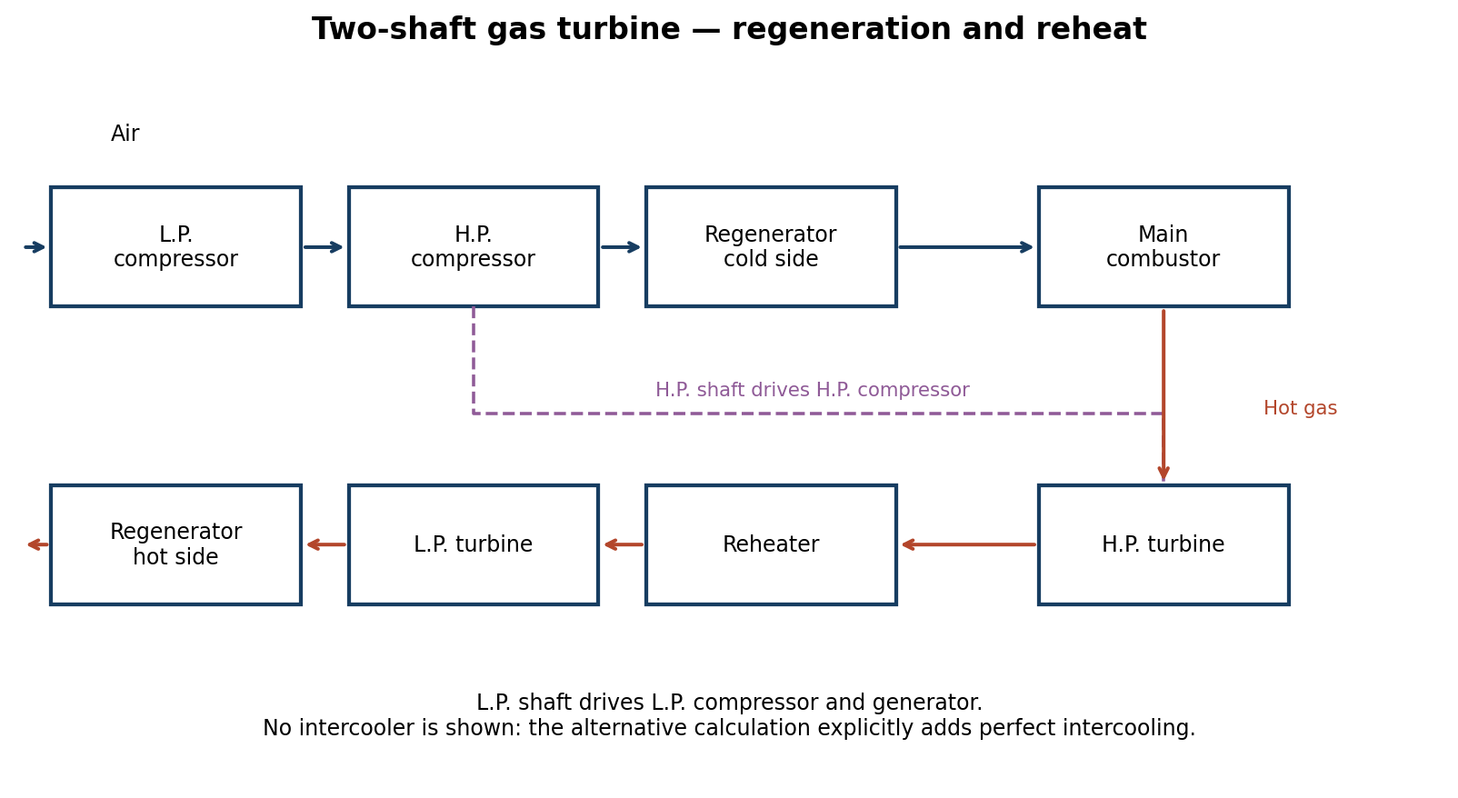
| Step | Formula / result |
|---|---|
| L.P. compressor outlet | T₂ = T₁{1 + [3^((γa−1)/γa) − 1]/ηc} = 424.9739 K. |
| H.P. compressor outlet | T₃ = T₂{1 + [3^((γa−1)/γa) − 1]/ηc} = 616.0764 K. |
| Compressor specific works | wc,L = 1.005(T₂ − 293.15) = 132.4830 kJ/kg; wc,H = 1.005(T₃ − T₂) = 192.0580 kJ/kg. |
| H.P. turbine balance | 1.14(873.15 − T₄) = wc,H ⇒ T₄ = 704.6780 K. |
| Isentropic H.P. turbine exit | T₄s = 873.15 − (873.15 − T₄)/0.9 = 685.9589 K. |
| Turbine pressure ratios | rp,H = (873.15/T₄s)^(γg/(γg−1)) = 2.632846; rp,L = 9/rp,H = 3.418354. |
| L.P. turbine outlet | T₆ = 873.15{1 − 0.9[1 − rp,L^−((γg−1)/γg)]} = 665.7811 K. |
| Regenerator air outlet | Tregen = T₃ + 0.7(T₆ − T₃) = 650.8697 K. |
| Net specific output | wnet = 1.14(873.15 − T₆) − wc,L = 103.9176 kJ/kg. H.P. turbine work already balances H.P. compressor work. |
| (i) Net power | 115 × 103.9176 = 11950.525 kW = 11.9505 MW. |
| Heat addition, main combustion plus reheat | qin = 1.14(873.15 − Tregen) + 1.14(873.15 − T₄) = 445.4576 kJ/kg. |
| (ii) Thermal efficiency | η = wnet/qin = 23.3283%. |
| Declared assumption | Net power | Thermal efficiency |
|---|---|---|
| No intercooling, used above | 11.9505 MW | 23.3283% |
| If perfect intercooling to 20°C is additionally intended | 17.8690 MW | 31.8887% |
The second line is conditional: perfect intercooling is extra information, not stated in the printed question.
Question 6(a)
During an engine trial, the volumetric analysis of the dry flue gas gave the following results: CO₂ = 13%; CO = 0.3%; O₂ = 6%; N₂ = 80.7%. The ultimate analysis of the flue gases was reported as follows: C = 62.4%; H₂ = 4.2%; O₂ = 4.5%; moisture = 15%; ash = 13.9%. Calculate the: (i) minimum air required to burn 1 kg of fuel; (ii) actual mass of air supplied per kg of fuel; (iii) amount of excess air supplied per kg of fuel. Take atomic mass as C = 12, O₂ = 16 and H₂ = 1.
(10 marks)
Answer
Interpret the C/H/O/moisture/ash percentages as the ultimate fuel analysis: ash and fuel moisture do not describe a dry-gas composition. Use conventional dry air with 23% oxygen and 77% nitrogen by mass; neglect fuel nitrogen. The given 16 and 1 are atomic masses, so molecular masses O₂ and H₂ are 32 and 2.
| Step | Working / result |
|---|---|
| Oxygen for carbon | (32/12) × 0.624 = 1.664 kg O₂/kg fuel. |
| Oxygen for hydrogen | 8 × 0.042 = 0.336 kg O₂/kg fuel. |
| Deduct oxygen already in fuel | O₂,min = 1.664 + 0.336 − 0.045 = 1.955 kg/kg fuel. |
| (i) Minimum air | 1.955/0.23 = 8.500 kg air/kg fuel. |
| Basis: 100 kmol dry products | Carbon in CO₂ + CO = (13 + 0.3) × 12 = 159.6 kg. |
| Fuel burned on this basis | 159.6/0.624 = 255.76923 kg fuel. |
| Nitrogen from supplied air | 80.7 × 28 = 2259.6 kg N₂. |
| (ii) Actual air | 2259.6/(0.77 × 255.76923) = 11.47341 kg air/kg fuel. |
| (iii) Excess air | 11.47341 − 8.500 = 2.97341 kg air/kg fuel. |
| Percentage excess | 100(11.47341/8.500 − 1) = 34.9813%. |
The nitrogen balance uses all supplied dry-gas readings without assuming CO is absent. Different declared standard air-composition constants give slightly different numerical values.
Question 6(b)
A two stage single acting reciprocating air compressor is to be designed to take air at 0.95 bar and 22°C, and deliver at 13 bar. It is anticipated that the volumetric efficiencies of both the high and low pressure stages will be 83% and the mechanical efficiency will be 85%. If the air mass flow rate is to be 0.017 kg/s and the compressor runs at 400 rev/min, calculate: (i) power required to drive the compressor; (ii) high pressure and low pressure cylinder swept volumes. Take the polytropic index as 1.4.
(10 marks)
Answer
Use absolute pressures, Rair = 0.287 kJ/(kg K), perfect intercooling back to 22°C and equal stage pressure ratios for the minimum-work design. Intercooler losses are neglected. These standard design assumptions are necessary because the intermediate pressure and intercooler performance are not otherwise specified.
| Step | Working / result |
|---|---|
| Stage ratio | r = √(13/0.95) = 3.699218. |
| Intermediate pressure | pi = √(0.95 × 13) = 3.514257 bar = 351.4257 kPa. |
| Specific indicated work | w = 2[n/(n−1)]RT₁[r^((n−1)/n) − 1] = 268.7114 kJ/kg. |
| (i) Shaft power | Pshaft = ṁw/ηmechanical = 0.017 × 268.7114/0.85 = 5.37423 kW. |
| Single-acting cycles per second | 400/60 = 6.666667. |
| L.P. swept volume per cycle | Vs,L = ṁRT₁/[p₁ηv(N/60)] = 0.002739449 m³ = 2.73945 litres. |
| H.P. swept volume per cycle | Vs,H = ṁRT₁/[piηv(N/60)] = 0.000740548 m³ = 0.740548 litres. |
Question 7(a)
A steel pipe carrying a process fluid has a bore of 150 mm and thickness 5 mm. The pipe is covered with a 50 mm layer of insulation of thermal conductivity 0.05 W/(m K). The thermal conductivity of the steel may be taken as 45 W/(m K) and the surface heat transfer coefficient as 35 W/(m² K) for the inner surface of the pipe and 7 W/(m² K) for the outside surface of the insulation. Assuming the process fluid temperature to be constant at 300°C and that of the ambient as 16°C, determine: (i) heat loss per length of the pipe; (ii) outside surface temperature.
(10 marks)
Answer
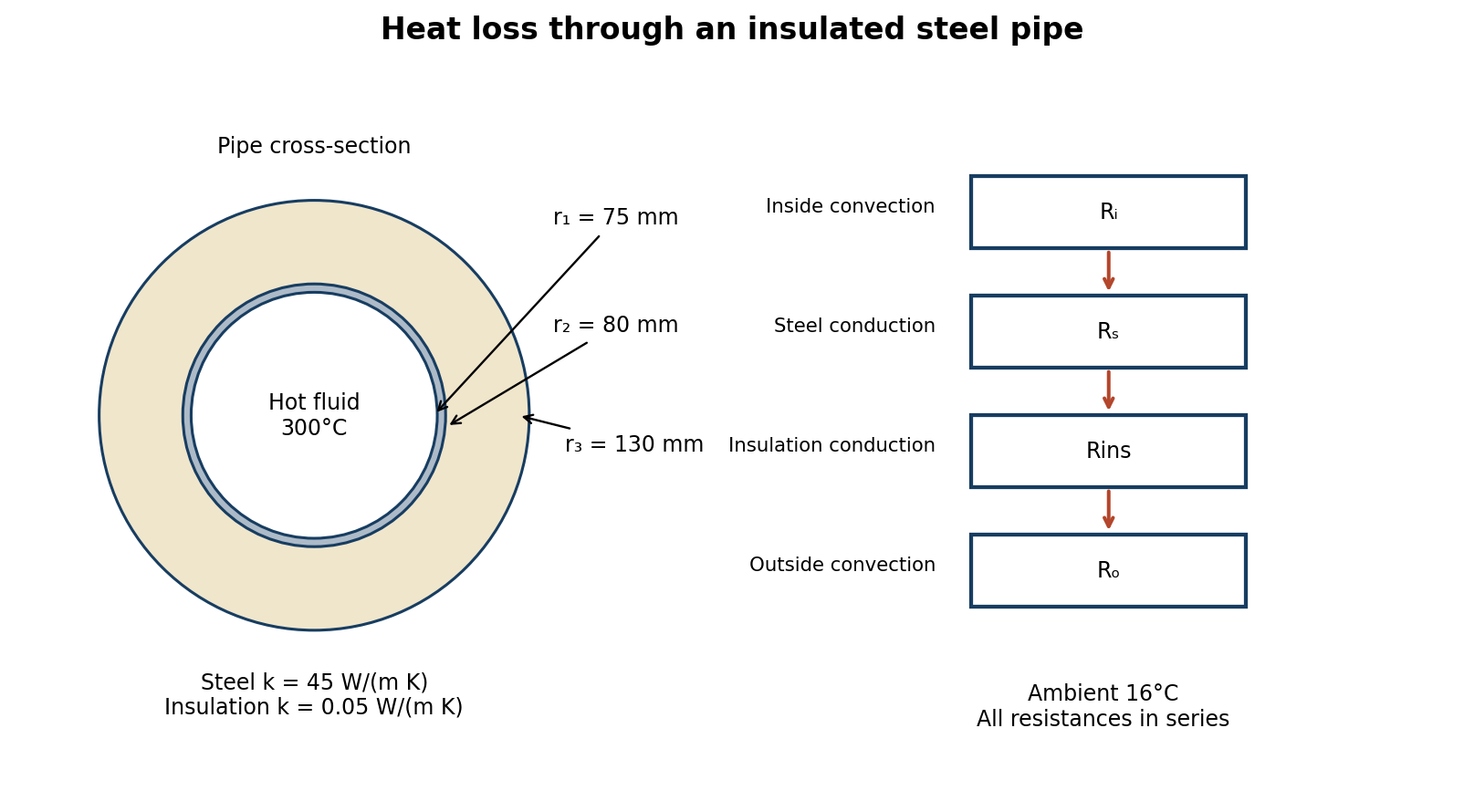
| Step | Formula / result for L = 1 m |
|---|---|
| Radii | r₁ = 0.075 m; r₂ = 0.080 m; r₃ = 0.130 m. |
| Inside film resistance | Ri = 1/(hi2πr₁L) = 0.06063045 K/W. |
| Steel resistance | Rs = ln(r₂/r₁)/(2πksL) = 0.00022826 K/W. |
| Insulation resistance | Rins = ln(r₃/r₂)/(2πkinsL) = 1.54541938 K/W. |
| Outside film resistance | Ro = 1/(ho2πr₃L) = 0.17489554 K/W. |
| Total resistance | Rt = 1.78117363 K/W for a one-metre length. |
| (i) Heat loss | q = (300 − 16)/Rt = 159.4454 W per metre. |
| (ii) Outside insulation surface | Tsurface = 16 + qRo = 43.8863°C. |
Question 7(b)
At the beginning of compression of an ideal diesel cycle, the gas temperature and pressure are 25°C and 1 bar. The volume ratio of compression is 16:1. The maximum cycle temperature is 1500°C. Determine the thermal efficiency of the cycle. Take Cp = 1.004 kJ/(kg K) and γ = 1.4.
(10 marks)
Answer
| Step | Working / result |
|---|---|
| Initial and maximum temperatures | T₁ = 298.15 K; T₃ = 1773.15 K. |
| Isentropic compression | T₂ = T₁r^(γ−1) = 298.15 × 16^0.4 = 903.8218 K. |
| Constant-pressure heat addition | Cut-off ratio ρc = V₃/V₂ = T₃/T₂ = 1.9618359. |
| Isentropic expansion to V₄ = V₁ | T₄ = T₃(ρc/r)^(γ−1) = 765.8832 K. |
| Specific heat at constant volume | Cv = Cp/γ = 0.717142857 kJ/(kg K). |
| Heat supplied | qin = Cp(T₃ − T₂) = 872.8055 kJ/kg. |
| Heat rejected | qout = Cv(T₄ − T₁) = 335.4315 kJ/kg. |
| Thermal efficiency | η = 1 − qout/qin = 0.61568583 = 61.5686%. |