Control Systems and Instrumentation — June/July 2024
KNEC Diploma in Mechanical Engineering — Module III. Paper code: 2501/302. Time: 3 hours.
These independent revision answers are not official KNEC marking schemes. Attempt each question before reading its answer. All optional questions are included for study.
Production option. Answer FIVE questions, choosing at least TWO from Section A (Questions 1–4) and at least TWO from Section B (Questions 5–8). Each whole question carries 20 marks.
All eleven original question figures are retained alongside complete answers. The actual filtered PD circuit, the rotational modelling assumption and the differential-pressure reference are explained explicitly.
Question 1(a)
State: (i) three features of a closed-loop control system; (ii) two merits of the control system in (a)(i).
(5 marks)
Answer
- Output is measured by a feedback element.
- A comparator forms an error between reference and measured feedback.
- A controller acts on that error to adjust the process input.
Two merits: suitable negative feedback reduces steady-state error and reduces the effect of disturbances or plant-parameter changes. These benefits require a properly designed stable loop.
Question 1(b)
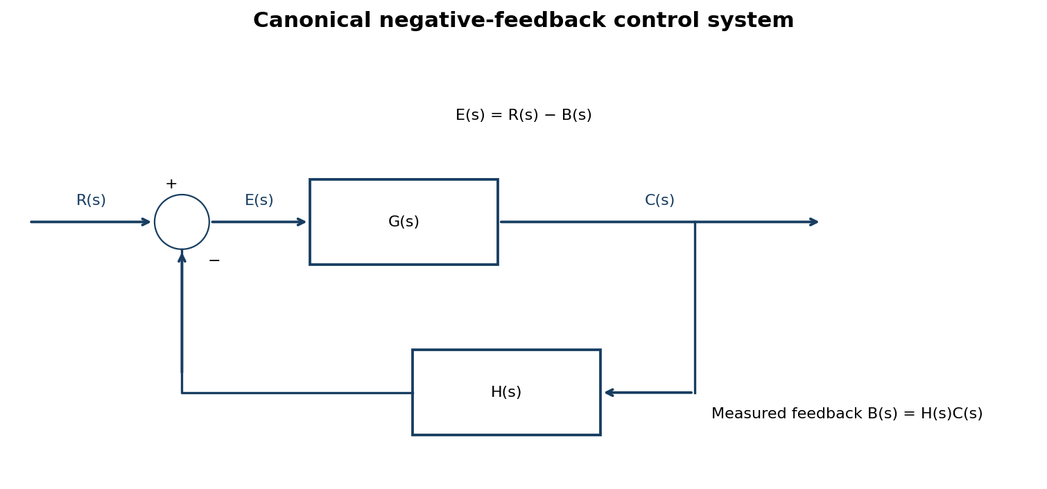
With the aid of a canonical block diagram of a control system, derive the expression for feedback transfer function.
(7 marks)
Answer
| Step | Working |
|---|---|
| Feedback signal | B(s) = H(s)C(s). |
| Error at comparator | E(s) = R(s) − B(s) = R(s) − H(s)C(s). |
| Forward path | C(s) = G(s)E(s) = G(s)R(s) − G(s)H(s)C(s). |
| Collect the output | [1 + G(s)H(s)]C(s) = G(s)R(s). |
| Closed-loop transfer function | C(s)/R(s) = G(s)/[1 + G(s)H(s)]. |
| Related feedback transfer | B(s)/R(s) = G(s)H(s)/[1 + G(s)H(s)]. For unity feedback H = 1, C/R = G/(1 + G). |
Question 1(c)
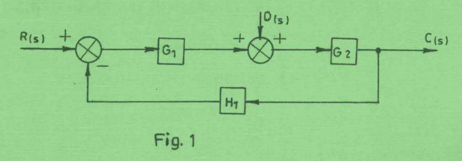
Figure 1 shows a block diagram of a multiple-input single-output (MISO) control system. Determine the expression for C(s).
(8 marks)
Answer
| Signal relation | Working |
|---|---|
| First summing point | E = R − H₁C. |
| Input of G₂ | V = G₁E + O, where O(s) is the additive second input shown above the summing point. |
| Output | C = G₂[G₁(R − H₁C) + O]. |
| Collect C | (1 + G₁G₂H₁)C = G₁G₂R + G₂O. |
| Required expression | C(s) = [G₁G₂/(1 + G₁G₂H₁)]R(s) + [G₂/(1 + G₁G₂H₁)]O(s). |
The reference and additive input share the same closed-loop denominator. The additive input passes through G₂ only before reaching the output.
Question 2(a)
Define each of the following as used in signal flow graph (SFG): (i) path; (ii) source node; (iii) gain.
(3 marks)
Answer
| Term | Definition |
|---|---|
| Path | A sequence of connected branches traversed in the direction of their arrows, without passing through any node more than once. |
| Source node | A node with outgoing branches only; it represents an independent input. |
| Gain | The branch transmittance multiplying a signal as it travels from one node to another. A path gain is the product of its branch gains. |
Question 2(b)
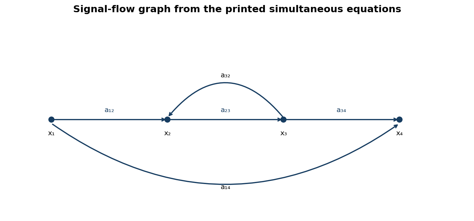
Figure 2 shows a forward path of a SFG for a control system described by: x₂ = a₁₂x₁ + a₃₂x₃; x₃ = a₂₃x₂; x₄ = a₃₄x₃ + a₁₄x₁. Draw the signal flow graph.

(6 marks)
Answer
| Branch | Gain |
|---|---|
| x₁ → x₂ | a₁₂ |
| x₃ → x₂ | a₃₂ |
| x₂ → x₃ | a₂₃ |
| x₃ → x₄ | a₃₄ |
| x₁ → x₄ | a₁₄ |
Check: x₄/x₁ = a₁₄ + a₁₂a₂₃a₃₄/(1 − a₂₃a₃₂). The positive feedback branch has the plus sign given in the printed equation.
Question 2(c)
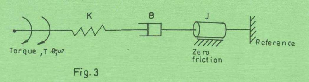
(i) Explain system modelling. (ii) Figure 3 shows a mechanical rotational system. (I) Write the torque equation; (II) determine the transfer function θo(s)/T(s).
(8 marks)
Answer
(i) System modelling is the construction of a mathematical representation of a physical system from its components, physical laws and stated assumptions, so that its behaviour can be analysed or predicted.
(ii) For the usual single-degree-of-freedom rotational load model, let J be inertia, B viscous rotational damping, K torsional stiffness and θo the common angular displacement. Opposing load torques are Jθ̈o, Bθ̇o and Kθo.
| Step | Working |
|---|---|
| Torque balance | T(t) = J d²θo/dt² + B dθo/dt + Kθo. |
| Laplace transform, zero initial conditions | T(s) = (Js² + Bs + K)Θo(s). |
| Transfer function | Θo(s)/T(s) = 1/(Js² + Bs + K). |
| Units | J: kg m²; B: N m s/rad; K: N m/rad. The support marked “zero friction” adds no extra bearing-friction torque. |
The printed sketch does not label separate angular coordinates at the spring, damper and inertia. The result above explicitly uses the standard common-displacement load interpretation. A literal multi-shaft series connection would require the missing shaft coordinates and connection conditions; its transfer function must not be inferred by treating all angular deflections as equal.
Question 2(d)
State three passive elements of an electrical network.
(3 marks)
Answer
- Resistor R: dissipates electrical energy as heat.
- Inductor L: stores energy in a magnetic field.
- Capacitor C: stores energy in an electric field.
Question 3(a)
Define the following with respect to process control system: (i) process variable; (ii) controlled variable; (iii) actuating signal.
(3 marks)
Answer
| Term | Definition |
|---|---|
| Process variable | A measurable physical quantity describing the process, such as temperature, pressure, flow or level. |
| Controlled variable | The particular process output that the control system seeks to keep at its reference or desired trajectory. |
| Actuating signal | The error signal formed by comparing the reference with the feedback measurement, which drives the controller. The controller output then operates the final control element. |
Question 3(b)
Describe the following elements of process control systems: (i) measuring element; (ii) evaluation element; (iii) final control element.
(6 marks)
Answer
| Element | Function and example |
|---|---|
| Measuring element | Senses the controlled quantity and converts it to a usable measurement signal; for example, a temperature sensor and transmitter. |
| Evaluation element | Compares the measured value with the reference and determines the corrective action according to the control law; for example, a PI controller. |
| Final control element | Physically changes the manipulated variable in response to the controller output; for example, a valve that changes steam flow to a heater. |
Question 3(c)
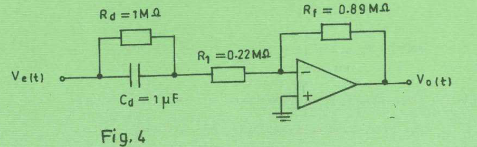
Figure 4 shows a proportional plus derivative (PD) controller. (i) Determine: (I) proportional gain Kp; (II) derivative time constant Kd; (III) derivative coefficient α. (ii) Write the expression for the output voltage Vout.
(8 marks)
Answer
Read all the printed components: Rd = 1 MΩ, Cd = 1 μF, R₁ = 0.22 MΩ and Rf = 0.89 MΩ. Assume an ideal op-amp. The parallel Rd–Cd network is in series with R₁; it is a practical filtered PD/lead network, not an unlimited ideal differentiator.
| Step | Working / result |
|---|---|
| Input impedance | Zin = R₁ + Rd/(1 + sRdCd). |
| Circuit transfer function | Vo/Ve = −Rf/Zin = −[Rf/(R₁ + Rd)](1 + sRdCd)/[1 + sR₁RdCd/(R₁ + Rd)]. |
| Specified parameter convention | Write Vo/Ve = −Kp(1 + Kd s)/(1 + αKd s). |
| (I) Proportional gain magnitude | Kp = Rf/(R₁ + Rd) = 0.89/1.22 = 0.729508. The circuit is inverting. |
| (II) Derivative time constant | Kd = RdCd = (1 × 10⁶)(1 × 10⁻⁶) = 1.000 s. |
| (III) Filter coefficient | α = R₁/(R₁ + Rd) = 0.22/1.22 = 0.180328; αKd = 0.180328 s. |
| (ii) Exact output relation | Vo(s) = −0.729508(1 + s)/(1 + 0.180328s) Ve(s). |
| Equivalent time-domain equation | vo(t) + 0.180328 dvo/dt = −0.729508[ve(t) + 1.000 dve/dt], with zero initial conditions. |
| Alternative derivative-gain convention | Vo/Ve = −Kp[1 + Td s/(1 + Tf s)] gives Tf = 0.180328 s and Td = (1 − α)Kd = 0.819672 s. Always state the chosen convention. |
Question 3(d)
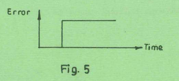
Figure 5 shows an error input signal to a proportional plus integral (PI) controller. Draw the corresponding response curve for the PI controller.
(3 marks)
Answer
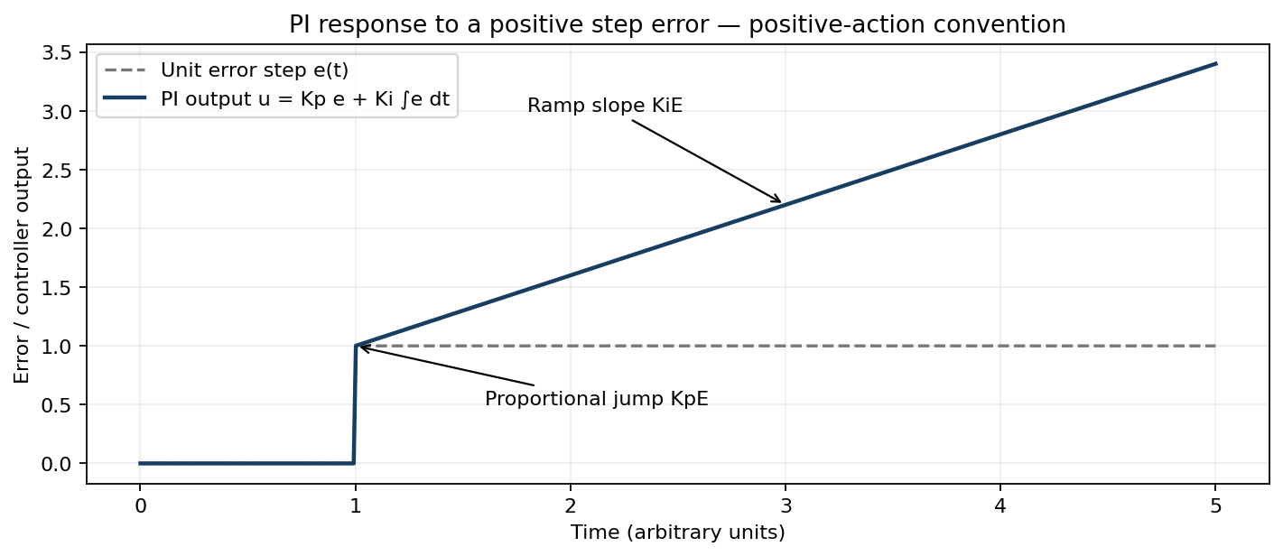
For a step error of height E at time t₀, u(t) = 0 before t₀ and u(t) = KpE + KiE(t − t₀) afterwards. Thus the output jumps by KpE and then ramps with slope KiE. For an inverting controller the corresponding output is reflected below the time axis.
Question 4(a)
State three basic components of servo-mechanism.
(3 marks)
Answer
- Error detector / comparator and feedback position sensor.
- Servo amplifier / controller.
- Servomotor / actuator driving the mechanical load.
Question 4(b)
Draw a labelled diagram of double-acting pneumatic cylinder.
(3 marks)
Answer
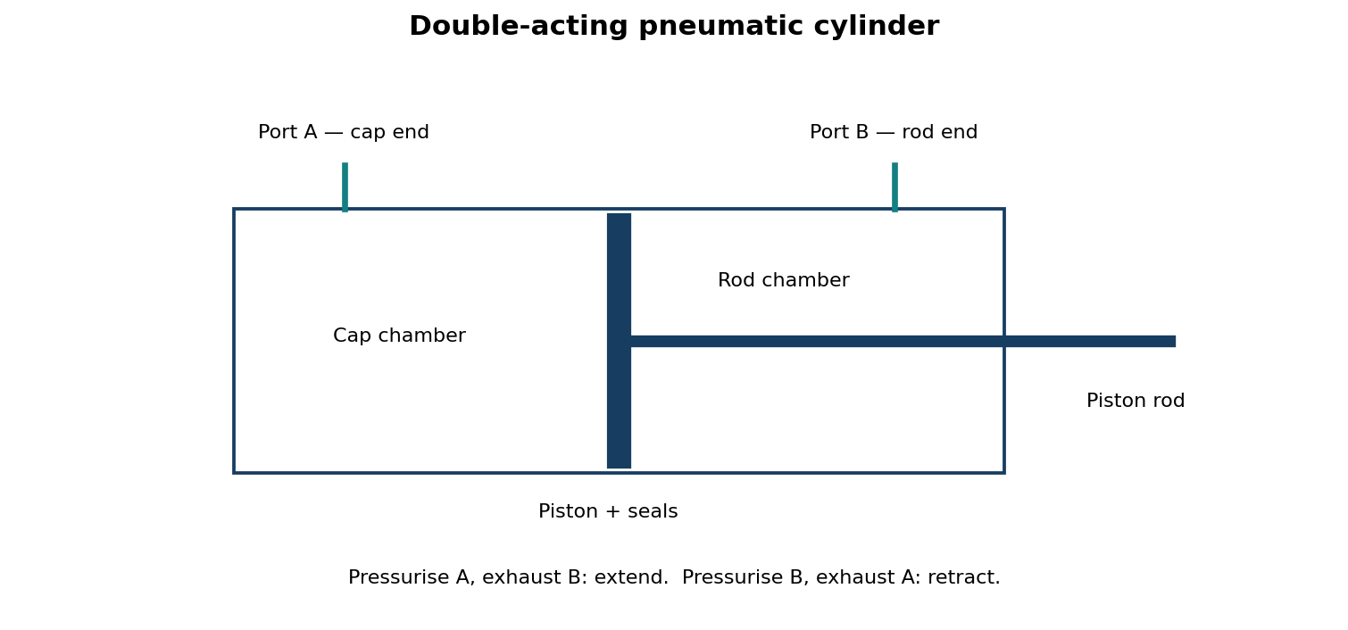
Question 4(c)
With the aid of a labelled diagram, explain the operation of a solenoid valve.
(6 marks)
Answer
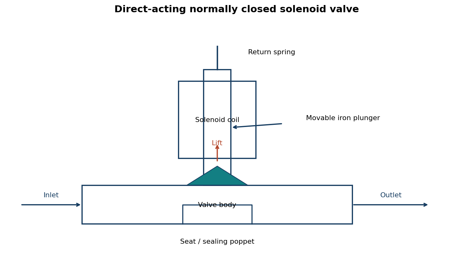
- With the coil de-energised, the spring holds the sealing poppet against its seat and blocks flow.
- When current flows in the coil, its magnetic field pulls the iron plunger into the coil, lifting the poppet from the seat.
- Fluid then passes from inlet to outlet. Removing current lets the spring return the poppet to the closed position.
A normally open valve reverses the default flow state; pilot-operated designs use the solenoid to operate a small pilot passage.
Question 4(d)
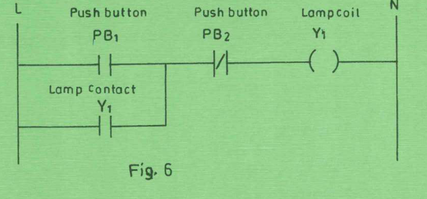
Figure 6 shows a programmable logic controller (PLC) ladder diagram program. (i) Describe the program operation sequence; (ii) write instruction listing program.
(8 marks)
Answer
(i) PB₁ is the normally open start condition, PB₂ is an inverted/stop condition and Y₁ is both the lamp output and its seal-in contact. Pressing PB₁ while the stop condition is false energises Y₁. Its parallel contact closes to maintain the lamp after PB₁ is released. Operating PB₂ breaks the logical continuity and turns the lamp off; the seal-in contact then opens.
| Instruction | Meaning |
|---|---|
| LD PB1 | Load start input. |
| OR Y1 | Parallel holding contact. |
| ANI PB2 | AND NOT stop input. |
| OUT Y1 | Write the lamp coil. |
The Boolean relation is Y₁,new = (PB₁ OR Y₁,old) AND NOT PB₂. This listing follows the contact logic as drawn. Actual field stop-button wiring and input polarity must be mapped consistently with the PLC input definition.
Question 5(a)
State two areas of application of platinum resistance temperature detector (RTD).
(3 marks)
Answer
- Accurate industrial process-temperature measurement and control, for example in chemical vessels, ovens or heat exchangers.
- Reference or calibration temperature measurement in laboratories and precision test equipment.
Question 5(b)
With the aid of a labelled constructional diagram, explain the operation of platinum resistance temperature detector (RTD).
(6 marks)
Answer
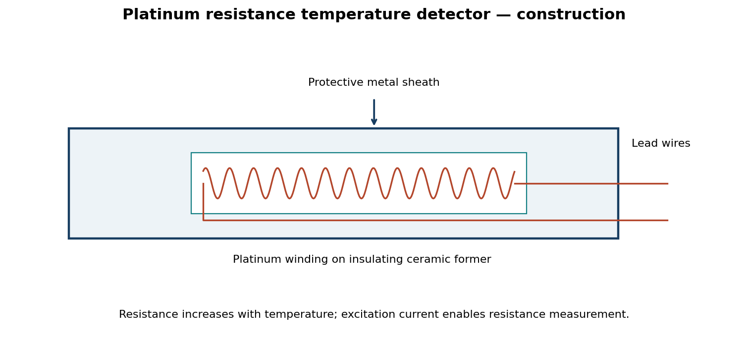
A small known current is passed through the platinum element. Its resistance rises reproducibly as its temperature rises, so the measured voltage gives R = V/I and a calibrated resistance–temperature relation gives temperature. Over a limited interval R ≈ R₀[1 + α(T − T₀)]; precision instruments use a fuller calibration equation. The sheath protects the element, insulation prevents electrical contact to the sheath, and three- or four-wire connections reduce lead-resistance error. Keep excitation low enough to limit self-heating.
Question 5(c)
The resistance of a thermistor is 5 kΩ at 20°C and 1 kΩ at 100°C. The relationship is R₂ = R₁ exp[β(1/T₂ − 1/T₁)], where temperatures are in kelvin and β is the sensitivity. Determine: (i) the value of β; (ii) resistance at 60°C.
(6 marks)
Answer
| Step | Working / result |
|---|---|
| Absolute temperatures | T₁ = 293.15 K; T₂ = 373.15 K; T₆₀ = 333.15 K. |
| Take logarithms | ln(R₂/R₁) = β(1/T₂ − 1/T₁). |
| (i) Sensitivity parameter | β = ln(1000/5000)/(1/373.15 − 1/293.15) = 2200.683 K. |
| (ii) Resistance at 60°C | R₆₀ = 5000 exp[2200.683(1/333.15 − 1/293.15)] = 2030.129 Ω ≈ 2.03013 kΩ. |
The resistance lies between the two supplied values and decreases with rising temperature, as expected for the stated negative-temperature-coefficient model.
Question 5(d)
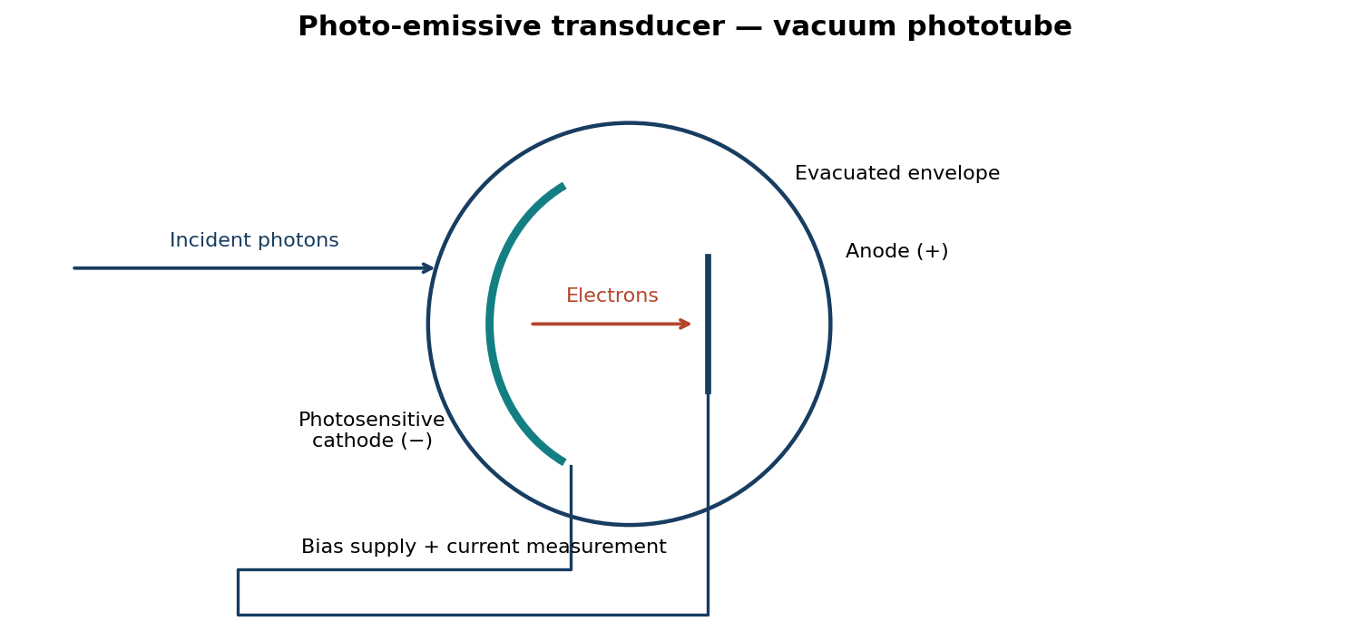
(i) Explain the photo-emissive effect. (ii) Draw a labelled construction diagram of a photo-emissive transducer.
(5 marks)
Answer
(i) The photo-emissive effect is emission of electrons from a material surface when incident photons transfer sufficient energy to overcome its work function. With a suitable positive collector, the emitted electrons produce a measurable photocurrent.
Question 6(a)
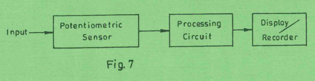
(i) Differentiate between absolute pressure and gauge pressure. (ii) Figure 7 shows a block diagram of a pressure measuring system. Describe the function of each component.
(8 marks)
Answer
(i) Absolute pressure is measured relative to a perfect vacuum. Gauge pressure is measured relative to the local atmospheric pressure: pabs = pgauge + patm.
| Component | Function |
|---|---|
| Potentiometric sensor | A pressure-sensitive diaphragm or bellows moves a potentiometer wiper. The resulting resistance or divider-voltage change represents pressure. |
| Processing circuit | Excites the potentiometer, conditions and amplifies the signal, filters noise and applies calibration or linearisation as needed. |
| Display / recorder | Converts the conditioned signal into a readable pressure indication and/or stores its variation with time. |
Question 6(b)
(i) Define humidity. (ii) Describe the method of transduction of: (I) optical hygrometer; (II) gravimetric hygrometer; (III) capacitive hygrometer.
(4 marks)
Answer
Humidity describes the water-vapour content of a gas. Relative humidity is the ratio of actual water-vapour partial pressure to the saturation pressure at the same temperature, expressed as a percentage.
| Method | Transduction |
|---|---|
| Optical | In a chilled-mirror instrument, condensation changes the mirror’s reflected light. The mirror temperature at the detected dew point determines vapour pressure and humidity. Optical absorption instruments instead measure water-vapour absorption at selected wavelengths. |
| Gravimetric | A measured quantity of gas passes through an absorbing/desiccant material; the increase in its mass gives the mass of water removed and hence humidity. |
| Capacitive | A hygroscopic dielectric absorbs or releases moisture, changing its permittivity and therefore the capacitance between electrodes. An electronic circuit converts that capacitance to a humidity indication. |
Question 6(c)
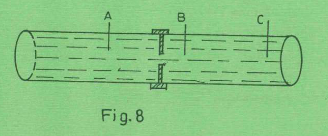
Figure 8 shows a pipeline section with an orifice plate. Describe the pressure at points A, B and C.
(4 marks)
Answer
For left-to-right flow, A is upstream: velocity is relatively low and static pressure is high. Near B, just downstream of the restriction and towards the vena contracta, the jet speed is high and static pressure is lowest. At C the flow expands and slows, so static pressure partly recovers, but irreversible losses mean it remains below the upstream pressure. Thus pA > pC > pB for the intended tapping locations.
Question 6(d)
With the aid of a labelled diagram, explain flow rate measurement using venturi tube.
(4 marks)
Answer
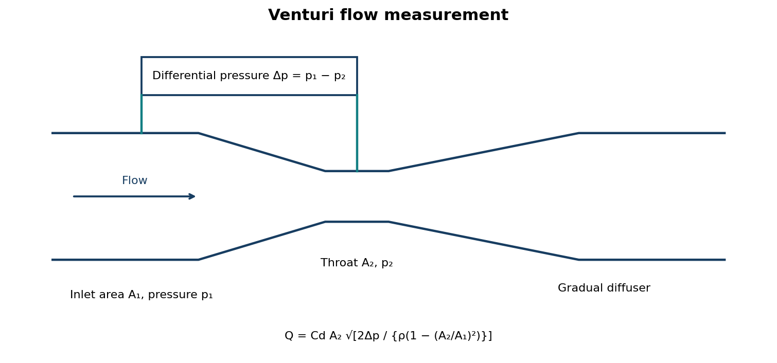
The converging section accelerates the flow into the throat, reducing its static pressure. A differential-pressure instrument measures Δp between the upstream section and throat. With known areas and fluid density, the pressure difference gives Q = Cd A₂√{2Δp/[ρ(1 − (A₂/A₁)²)]}. Cd accounts for real-flow losses; the gradual diffuser recovers part of the pressure.
Question 7(a)
Differentiate between operational errors and environmental errors with respect to electrical measuring instruments, citing one example in each case.
(4 marks)
Answer
| Error category | Meaning | Example |
|---|---|---|
| Operational | Error caused by how the operator selects, connects or reads the instrument. | Parallax when reading an analogue pointer, or selecting the wrong meter range. |
| Environmental | Error caused by external conditions influencing the instrument or measurement. | Temperature changing a resistance reading, or an external magnetic field deflecting a meter movement. |
Question 7(b)
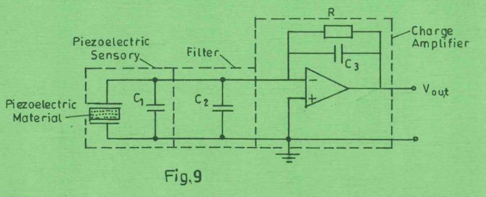
(i) List three types of piezoelectric materials. (ii) Figure 9 shows an equivalent schematic circuit of a piezoelectric transducer. Explain its working principle.
(8 marks)
Answer
(i) Quartz, Rochelle salt and lead zirconate titanate (PZT) ceramic.
- Mechanical force or stress applied to the piezoelectric material generates electric charge; over the linear operating range q = dF for a suitable piezoelectric coefficient d.
- C₁ represents the sensor capacitance and C₂ the input/cable or filtering capacitance shown in the circuit. Their capacitances affect unbuffered voltage sensitivity.
- The charge amplifier holds the input near virtual ground and transfers the generated charge to feedback capacitor C₃. Over its useful frequency range vo ≈ −q/C₃.
- The feedback resistor R provides a discharge path and sets the low-frequency time constant RC₃. The circuit is suited to changing force, vibration or pressure; charge leakage prevents indefinite measurement of a perfectly constant force.
Question 7(c)
A stress-strain sensor is used in testing strength of a material sample of length 2.5 cm. A stress of 98 MN/m² caused the sample to elongate to 2.515 cm. Determine: (i) strain; (ii) Young’s modulus of elasticity.
(6 marks)
Answer
| Step | Working / result |
|---|---|
| Extension | ΔL = 2.515 − 2.500 = 0.015 cm = 0.00015 m. |
| (i) Engineering strain | ε = ΔL/L₀ = 0.015/2.5 = 0.006 = 0.6%, dimensionless. |
| (ii) Young’s modulus | E = σ/ε = 98 × 10⁶/0.006 = 1.633333 × 10¹⁰ Pa = 16.3333 GPa. |
Young’s modulus interpretation assumes the measured point lies in the linear elastic region.
Question 7(d)
Explain the function of controlling instruments.
(2 marks)
Answer
A controlling instrument compares a measured process variable with a desired value and sends a corrective signal to a final control element, so that the process variable is maintained near the required value. For example, a temperature controller adjusts a heater or steam valve.
Question 8(a)
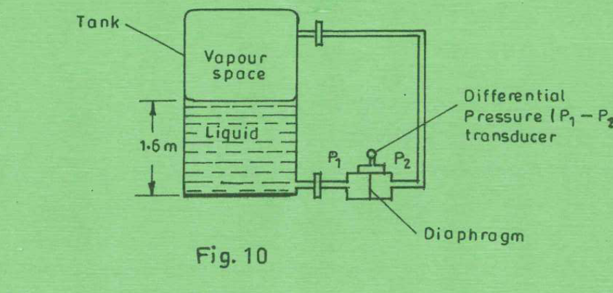
Figure 10 shows a set-up for level measurement of a liquid of density 0.92 g/cm³. (i) Describe its operation; (ii) determine the pressure at the bottom of the tank when the level is 1.6 m. Take g = 9.8 N/kg.
(8 marks)
Answer
(i) The high-pressure port is connected to the bottom tapping and the low-pressure port to the vapour space. For a dry reference leg with negligible gas-column head, vapour pressure acts on both ports and cancels: Δp = p₁ − p₂ = ρgh. Diaphragm deflection is converted to an electrical signal calibrated in liquid level.
| Step | Working / result |
|---|---|
| Convert density | 0.92 g/cm³ = 920 kg/m³. |
| (ii) Hydrostatic differential | Δp = 920(9.8)(1.6) = 14425.6 Pa = 14.4256 kPa. |
| Bottom pressure | pbottom = pvapour + 14.4256 kPa. The absolute bottom pressure cannot be found unless the vapour-space pressure is specified. |
| Level calibration | h = Δp/(ρg); a filled/wet reference leg would require a reference-head correction. |
Question 8(b)
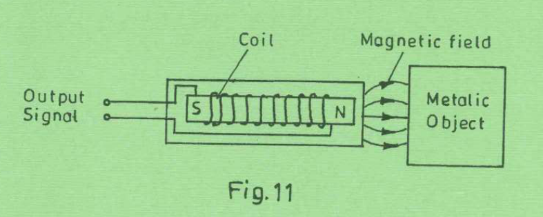
Figure 11 shows a sensor at close range to a metallic object. (i) Identify the type of sensor; (ii) list two types of metals it can detect; (iii) explain how the output signal is generated.
(6 marks)
Answer
(i) An inductive magnetic / variable-reluctance pickup, represented by a coil on a magnetic pole piece. (ii) Ferromagnetic targets such as iron and mild steel.
(iii) As the target approaches, leaves or moves past the pole, the reluctance of the magnetic circuit changes and hence the flux linking the coil changes. Faraday’s law gives an induced output e = −N dΦ/dt, which can be conditioned as a pulse or position-passage signal. A passive permanent-magnet pickup needs changing flux; it does not produce a sustained induced voltage from a motionless target. An actively excited inductive proximity sensor can detect a stationary target through a change in coil/oscillator behaviour, but that excitation circuit is not shown.
Question 8(c)
State three factors that affect performance of a capacitive type of sensor.
(3 marks)
Answer
- Effective overlapping plate area A.
- Plate separation d and its mechanical stability.
- Dielectric permittivity ε, including changes caused by material, moisture or temperature.
Question 8(d)
A capacitive sensor consists of two parallel plates of area 4.8 cm². The distance between the plates is 0.4 cm and the permittivity ε = 46.3 × 10⁻¹² F/m. Determine its capacitance.
(3 marks)
Answer
| Step | Working / result |
|---|---|
| SI geometry | A = 4.8 × 10⁻⁴ m²; d = 0.4 × 10⁻² = 0.004 m. |
| Parallel-plate capacitance | C = εA/d = (46.3 × 10⁻¹²)(4.8 × 10⁻⁴)/0.004 = 5.556 × 10⁻¹² F = 5.556 pF. |
The given permittivity is absolute permittivity, so do not multiply by ε₀ again. Fringing is neglected.