Control Systems and Instrumentation — October/November 2023
KNEC Diploma in Mechanical Engineering — Module III. Paper code: 2501/302; also 2503/302, 2508/302, 2509/302. Time: 3 hours.
Questions are transcribed from the supplied examination paper. The independent revision answers are not official KNEC marking schemes. All eight questions, including optional questions, are answered.
Answer FIVE questions by choosing at least TWO questions from each of Section A: Control Systems and Section B: Instrumentation. All questions carry equal marks.
The supplied paper omits the lower ADC temperature limit in Question 5(b). Question 8(b) combines a “push-pull” description with a sliding-dielectric drawing; the worked answer states its geometric interpretation. Printed wording, numerical data and marks are retained.
Question 1(a)
Differentiate between controlled variable and reference variable with respect to control systems.
(4 marks)
Answer
| Variable | Meaning |
|---|---|
| Controlled variable | Actual process output being regulated, such as measured room temperature. |
| Reference variable | Desired value or set-point against which the measured output is compared. The difference generates the error. |
Question 1(b)
Table 1 shows examples of control systems. Classify them as either open-loop or closed-loop control system.
| Control systems | Types of control (closed or open loop) |
|---|---|
| Fuel injection system in automobile engine | |
| Car speed governor | |
| Air conditioner | |
| CNC machine operation |
(4 marks)
Answer
| System | Classification and feedback |
|---|---|
| Fuel injection system in automobile engine | Closed-loop when oxygen/exhaust feedback corrects the air–fuel ratio. Fuel injection also has open-loop operating modes; the description alone does not specify the implementation. |
| Car speed governor | Closed-loop: measured speed is fed back and the fuel/throttle setting changes to correct speed error. |
| Air conditioner | Closed-loop when a thermostat measures room temperature and controls cooling. |
| CNC machine operation | Closed-loop for servo axes with encoder position feedback. An unmonitored stepper-axis CNC is open-loop. CNC alone does not establish the loop type. |
The usual examination examples assume feedback-regulated fuel injection, thermostatic air conditioning and servo CNC. State these assumptions instead of claiming every implementation uses feedback.
Question 1(c)
Define each of the following with reference to feedback control system: (i) load disturbance; (ii) manipulated variable; (iii) transfer function.
(3 marks)
Answer
- Load disturbance: an unwanted external influence that changes the process output, such as additional mechanical load on a speed-controlled motor.
- Manipulated variable: the process input deliberately adjusted by the controller, such as fuel flow or heater power.
- Transfer function: the Laplace-transform ratio of output to input for a linear time-invariant system with zero initial conditions.
Question 1(d)
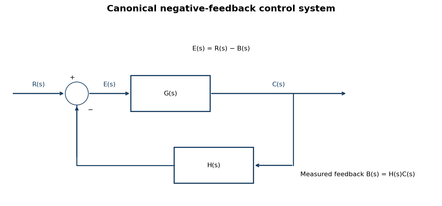
Figure 1 shows a block diagram of a control system. (i) reduce it to its conical form. (ii) determine its transfer function, C(s)/R(s).
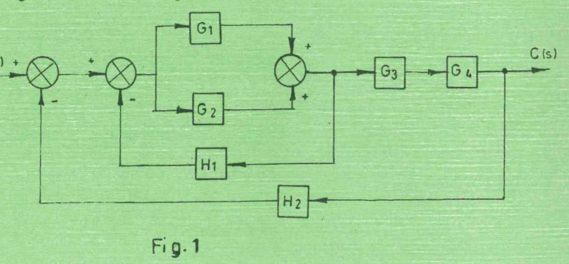
(9 marks)
Answer
| Step | Working |
|---|---|
| Parallel blocks | Let P = G₁ + G₂. Their outputs enter the third summing junction with positive signs. |
| Inner negative loop | If E₁ = R − H₂C and E₂ = E₁ − H₁V, then V = P E₂. Hence V/E₁ = P/(1 + PH₁). |
| Canonical forward block | G_eq = P G₃G₄/(1 + PH₁), with negative feedback H₂ from C to the first comparator. |
| Close the outer loop | C = G_eq(R − H₂C), so C/R = G_eq/(1 + G_eqH₂). |
| Answer | C(s)/R(s) = (G₁+G₂)G₃G₄ / [1 + (G₁+G₂)H₁ + (G₁+G₂)G₃G₄H₂]. |
Question 2(a)
Distinguish between each of the following with respect to signal flow graphs in control systems: (i) node and branch; (ii) forward path and feedback path.
(4 marks)
Answer
| Pair | First term | Second term |
|---|---|---|
| (i) | A node represents a system variable or signal. | A branch is a directed connection that multiplies the starting-node signal by its branch gain. |
| (ii) | A forward path follows branch directions from the input node to the output node without visiting a node twice. | A feedback path returns a signal from a downstream node to an earlier node; together with forward branches it can form a loop. |
Question 2(b)
Figure 2 shows a signal flow graph of a control system. Determine the: (i) forward paths gains; (ii) loops gains; (iii) forward paths determinants; (iv) transfer function, M.
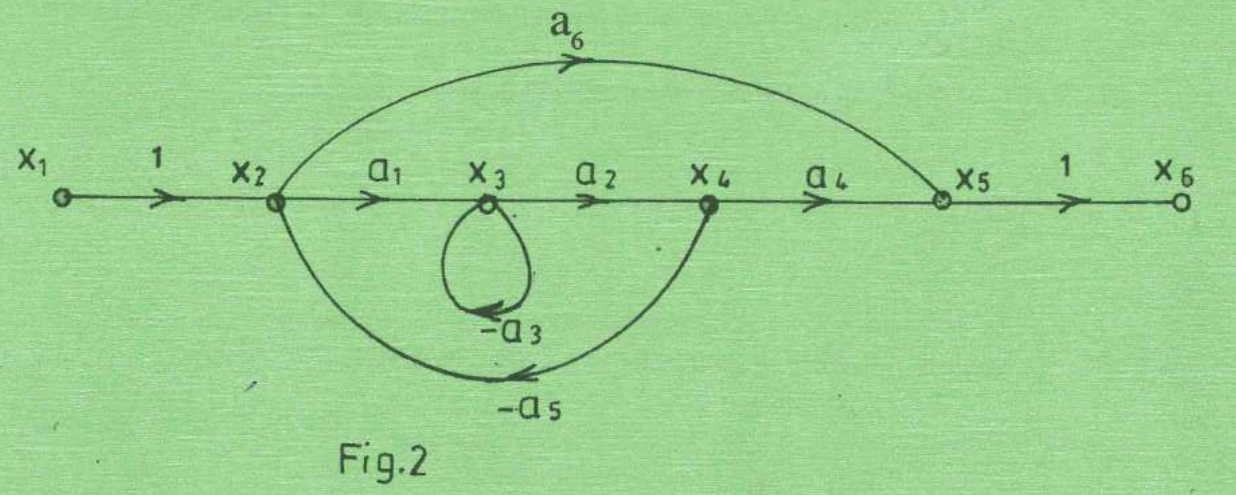
(9 marks)
Answer
| Step | Working |
|---|---|
| Forward paths | P₁ = a₁a₂a₄ along x₁→x₂→x₃→x₄→x₅→x₆; P₂ = a₆ along x₁→x₂→x₅→x₆. The end branches each have gain 1. |
| Loop gains | L₁ = −a₃, the self-loop at x₃; L₂ = −a₁a₂a₅ along x₂→x₃→x₄→x₂. |
| Non-touching loops | L₁ and L₂ touch at x₃, so there is no product of non-touching loops. |
| Graph determinant | Δ = 1 − (L₁+L₂) = 1 + a₃ + a₁a₂a₅. |
| Forward-path determinants | Δ₁ = 1 because both loops touch P₁. For P₂, L₁ does not touch the path, so Δ₂ = 1 − L₁ = 1 + a₃. L₂ touches x₂ and is removed. |
| Mason’s formula | M = (P₁Δ₁ + P₂Δ₂)/Δ. |
| Answer | M = [a₁a₂a₄ + a₆(1+a₃)]/[1+a₃+a₁a₂a₅]. |
Question 2(c)
Figure 3 shows an electrical R – L network. (i) Using Kirchoff’s laws, write the differential equations for the network. (ii) By Laplace transformation, determine the transfer function Vₒ(s)/Vᵢ(s).
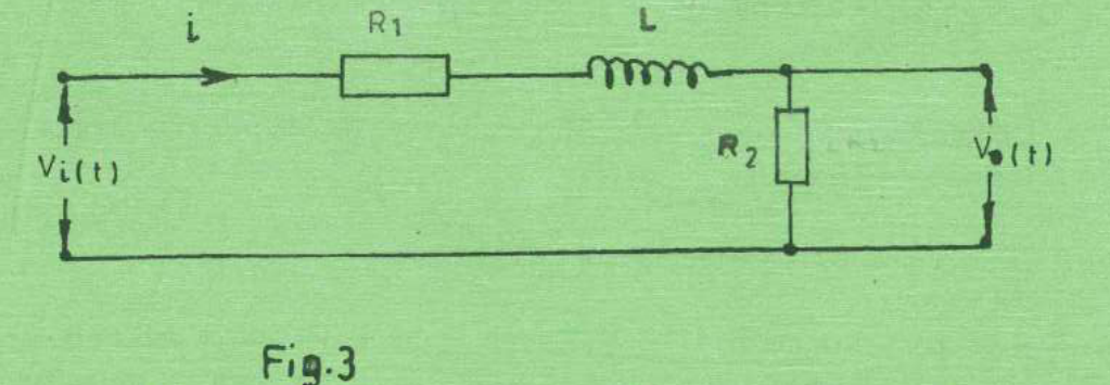
(7 marks)
Answer
| Step | Working |
|---|---|
| Kirchhoff voltage law | vᵢ(t) = R₁i(t) + L di/dt + R₂i(t). |
| Output equation | vₒ(t) = R₂i(t); equivalently L dvₒ/dt + (R₁+R₂)vₒ = R₂vᵢ. |
| Zero-initial-condition transform | Vᵢ(s) = (R₁+R₂+sL)I(s); Vₒ(s) = R₂I(s). |
| Answer | Vₒ(s)/Vᵢ(s) = R₂/(sL+R₁+R₂). The output is assumed unloaded as drawn. |
Question 3(a)
Define each of the following with respect to analogue controllers: (i) process load; (ii) process lag; (iii) dead time.
(3 marks)
Answer
- Process load: the demand placed on the process or operating condition that the control system must accommodate.
- Process lag: delay in the response caused by energy or material storage; the output approaches its new value gradually after an input change.
- Dead time: an interval after an input change during which its effect has not yet appeared at the measured output, often because of transport or measurement delay.
Question 3(b)
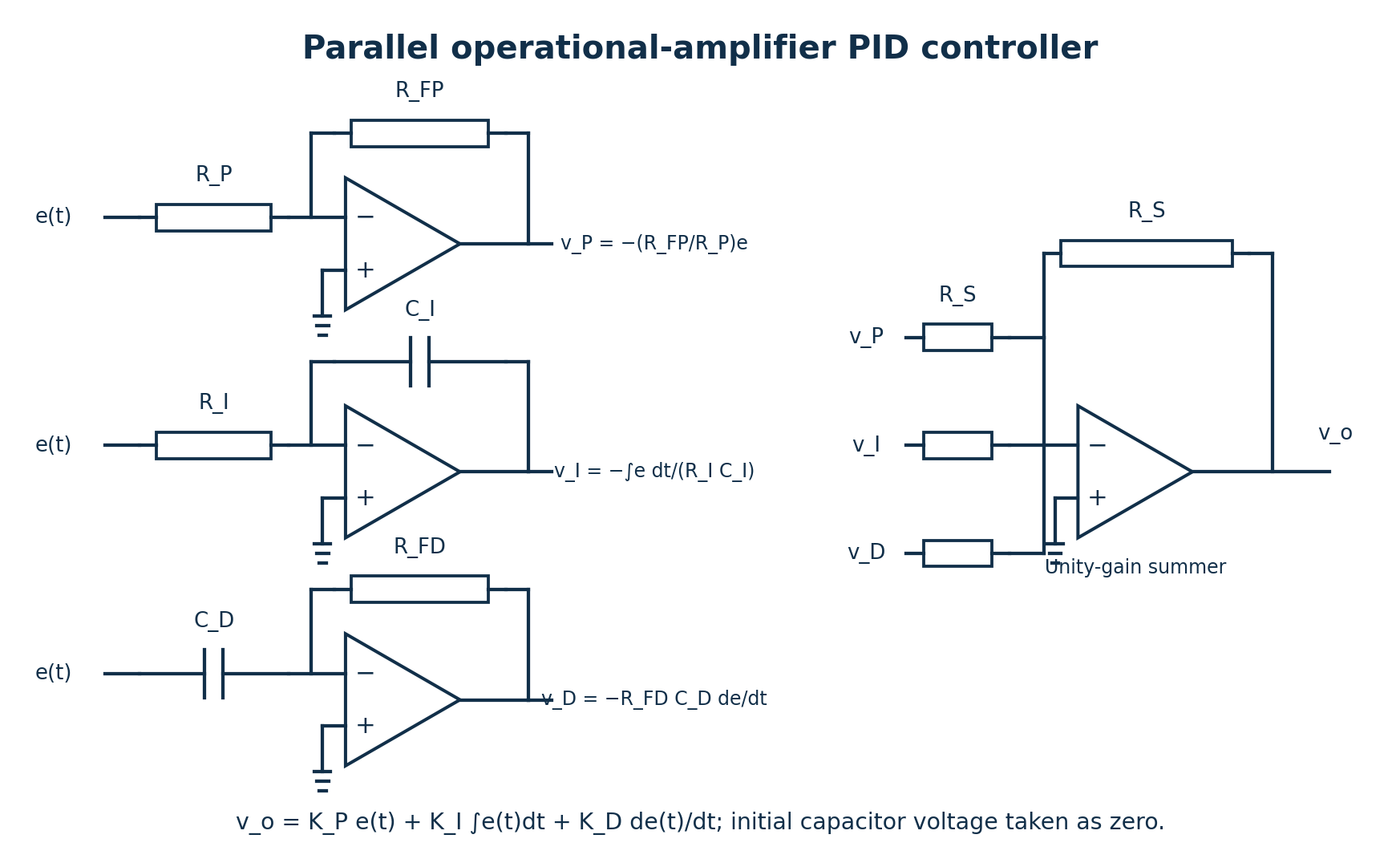
(i) Draw a labelled circuit diagram of operational amplifier based proportional plus integral plus derivative (PID) controller. (ii) Write the expression for the output voltage of the PID controller in (b) (i).
(7 marks)
Answer
| Step | Working |
|---|---|
| Proportional branch | v_P = −(R_FP/R_P)e(t). |
| Integral branch | v_I = −[1/(R_I C_I)]∫e(t)dt, with zero initial capacitor voltage. |
| Derivative branch | v_D = −R_FD C_D de(t)/dt. |
| Equal-resistor summing stage | vₒ = −(v_P+v_I+v_D). |
| Answer | vₒ(t) = K_P e(t) + K_I∫e(t)dt + K_D de(t)/dt; K_P = R_FP/R_P, K_I = 1/(R_I C_I), K_D = R_FD C_D. |
This is an ideal parallel PID circuit. A practical differentiator includes high-frequency roll-off, and an integrator includes limiting or anti-windup. The sign changes if the final inverting summer is omitted.
Question 3(c)
Describe each of the following process control strategies: (i) feed-forward strategy; (ii) feedback process strategy.
(4 marks)
Answer
- Feed-forward: measure a disturbance and use a process relationship to change the manipulated input before the disturbance produces an output error. For example, adjust heating when incoming liquid flow changes.
- Feedback: measure the controlled output, compare it with the set-point, and change the manipulated input in response to the resulting error. It can correct unmeasured disturbances after their effects reach the output.
Question 3(d)
Table 2 shows examples of process controls. Complete the table by indicating the process variable and manipulated variable in each case.
| Examples of process controls | Process variable | Manipulated variable |
|---|---|---|
| Furnace control for melting metals | ||
| Liquid overflow control inside an enclosed boiler | ||
| Hydraulic driven guillotine machine |
(6 marks)
Answer
| Process | Process variable | Manipulated variable |
|---|---|---|
| Furnace control for melting metals | Furnace/metal temperature | Fuel flow or electrical heating power. |
| Liquid overflow control inside an enclosed boiler | Boiler liquid level | Feedwater flow, adjusted by the inlet control valve or feed pump. |
| Hydraulic driven guillotine machine | Blade/cylinder position or cutting stroke, for position control | Hydraulic flow to the cylinder, adjusted through a directional/proportional valve. |
For a guillotine force-control loop, cutting force is the process variable and hydraulic pressure is the manipulated variable. The selected variable depends on the stated control objective; the paper does not specify that objective.
Question 4(a)
(i) State three categories of actuators. (ii) Explain the purpose of actuators in control systems.
(5 marks)
Answer
- Electrical actuators, such as motors and solenoids.
- Pneumatic actuators, powered by compressed gas.
- Hydraulic actuators, powered by pressurised liquid.
- An actuator converts a control command and supplied energy into physical movement or force, positioning the final control element or driving the controlled mechanism.
Question 4(b)
Outline four differences between a general purpose computer and a programmable logic controller (PLC).
(4 marks)
Answer
| Aspect | General purpose computer | PLC |
|---|---|---|
| Operating environment | Usually needs protection or added industrialisation for harsh plant conditions. | Designed for industrial temperature, electrical noise and vibration conditions within its rating. |
| Inputs and outputs | Normally requires suitable interface cards and isolation for plant sensors and actuators. | Provides rated industrial I/O modules with conditioning and isolation. |
| Execution | Typically uses a general-purpose operating system; deterministic timing needs additional design. | Uses cyclic scans or scheduled/event tasks with predictable control execution. |
| Programming and maintenance | Optimised for general computing, applications and extensive user interaction. | Optimised for plant logic, interlocks, timers and online diagnostics, commonly using IEC 61131-3 languages. |
Question 4(c)
Draw a labelled block diagram of a PLC system.
(6 marks)
Answer
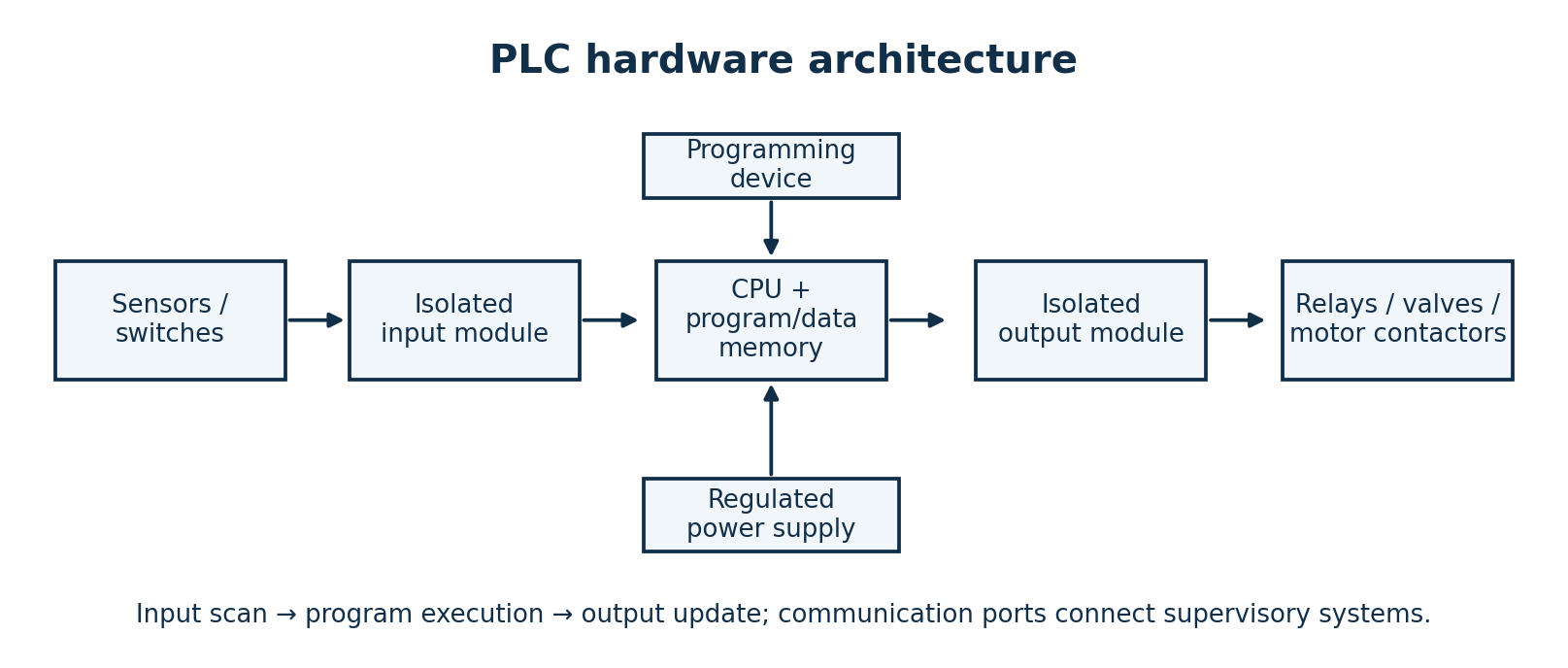
- Input modules isolate and condition field signals; the input image is read by the CPU.
- The CPU executes the stored control program using memory, timers and counters.
- Output modules drive suitable interfaces such as relay coils, contactors or valves. The PLC supply powers its electronics; actuator loads may require a separate rated supply.
- A programming device loads and monitors the program; communication ports exchange supervisory data.
Question 4(d)
A stepper motor makes 1000 steps per revolution. The motor makes 14,000 steps in the clockwise direction and 8,600 steps in the counter clockwise direction from a reference point. Determine the: (i) step angle; (ii) final position of the motor from the reference point.
(5 marks)
Answer
| Step | Working |
|---|---|
| Step angle | α = 360°/1000 = 0.36° per step. |
| Net signed steps | Take clockwise as positive: N = 14,000 − 8,600 = 5,400 steps. |
| Net accumulated rotation | θ = 5,400 × 0.36° = 1,944° clockwise = 5.4 revolutions. |
| Position within one revolution | 1,944° − 5 × 360° = 144° clockwise from the reference orientation. |
| Answer | Step angle 0.36°; accumulated displacement 1,944° clockwise, equivalent to final angular orientation 144° clockwise. |
Question 5(a)
State three merits of integrated circuit (IC) temperature sensors.
(3 marks)
Answer
- They provide a relatively linear, readily conditioned electrical output over their specified temperature range.
- They are compact and can incorporate amplification or digital conversion, reducing external component count.
- They offer useful sensitivity and convenient connection to electronic measurement and control circuits.
Question 5(b)
A 10-bit analogue -to – digital (ADC) temperature sensor measures temperature in the range of °C to 205 °C. Determine the: (i) resolution of the sensor; (ii) temperature value when the ADC output value is 800.
(5 marks)
Answer
Source issue: the supplied paper leaves the lower temperature limit blank before “°C”. Denote this missing value by T_min; a unique numerical temperature cannot be claimed without it.
| Step | Working |
|---|---|
| Number of codes | N = 2¹⁰ = 1024 codes, numbered 0 to 1023. |
| Quantisation interval | For a uniform ADC, q = (205−T_min)/1024 °C per code. |
| Code 800 | Using the lower-edge code convention: T ≈ T_min + 800(205−T_min)/1024. A code corresponds to an interval of width q; it is not an exact continuous temperature. |
| Conditional zero lower limit | If the missing lower limit is 0 °C, q = 205/1024 = 0.2001953125 °C per code and T ≈ 160.15625 °C. |
| Endpoint-calibration convention | If code 0 is assigned exactly to T_min and code 1023 exactly to 205 °C, q_end = (205−T_min)/1023. For T_min = 0, q_end = 0.2003910 °C/code and T(800) ≈ 160.3128 °C. |
| Answer | The main result must retain T_min. Either numerical set is conditional on a stated missing lower limit and conversion convention. |
Question 5(c)
(i) Explain the working principle of a pyroelectric sensor. (ii) State two merits of the sensor in c (i).
(6 marks)
Answer
Changing incident thermal radiation changes the temperature of the pyroelectric element. Its spontaneous electric polarisation changes, producing charge on electrodes. A high-input-impedance circuit converts this changing charge/current to a signal. Ideally i = pA(dT/dt), where p is the pyroelectric coefficient. Steady temperature gives no sustained ideal output; motion or optical modulation creates the required change.
- It detects changing infrared radiation without contacting the object.
- The sensing element generates charge without an external polarising supply; the complete sensor/readout electronics may still need power.
Question 5(d)
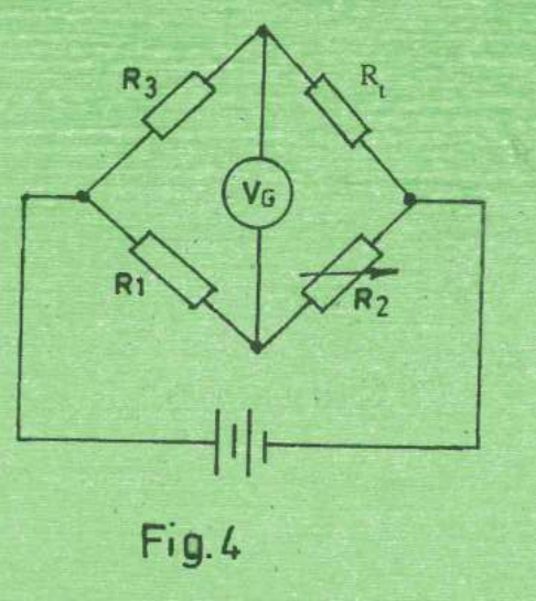
Figure 4 shows a wheat stone bridge circuit. The resistor Rₜ represents the resistance of a resistive type sensor. (i) Explain the balanced condition of the bridge. (ii) Given that R₁ = 250 Ω, R₂ = 28 Ω and R₃ = 310 Ω at a balanced condition, determine the value of Rₜ.
(6 marks)
Answer
| Step | Working |
|---|---|
| Balanced condition | The two detector terminals have equal potential, so V_G = 0 and no current flows through an ideal galvanometer. |
| Use the actual arm positions | Upper arms are R₃ and Rₜ; lower arms are R₁ and R₂. Balance therefore gives R₃/(R₃+Rₜ) = R₁/(R₁+R₂), or R₃R₂ = R₁Rₜ. |
| Substitute | Rₜ = R₃R₂/R₁ = 310 × 28/250. |
| Answer | Rₜ = 34.72 Ω. |
Question 6(a)
Define each of the following with respect to fluid flow in a pipeline: (i) pressure drop; (ii) laminar; (iii) shear stress.
(3 marks)
Answer
- Pressure drop: the decrease in fluid pressure between two pipeline locations; friction and local losses contribute, and elevation/velocity changes must be distinguished when interpreting measurements.
- Laminar: a flow regime in which fluid moves in orderly layers with little cross-layer mixing.
- Shear stress: tangential force per unit area acting between adjacent fluid layers or between the fluid and a wall; for a Newtonian fluid τ = μ du/dy.
Question 6(b)
Describe the working principle of each of the following types of viscometers: (i) torque technique; (ii) oscillation.
(6 marks)
Answer
- Torque technique: rotate a spindle or cylinder at a known speed while immersed in the sample. Viscous shear resists rotation; measure the required torque. For a known geometry, speed and calibrated flow regime, the torque determines viscosity. For non-Newtonian samples report apparent viscosity at the relevant shear rate.
- Oscillation: excite a probe, plate or torsional element into vibration in the sample. Viscous interaction damps its motion and changes amplitude, phase or the power needed to sustain vibration. Calibrate that response against viscosity; some instruments also require density or measure a viscosity–density product.
Question 6(c)
(i) With the aid of a labelled diagram, describe the operation of a turbine type flowmeter. (ii) Outline two merits of turbine type flow meters.
(9 marks)
Answer
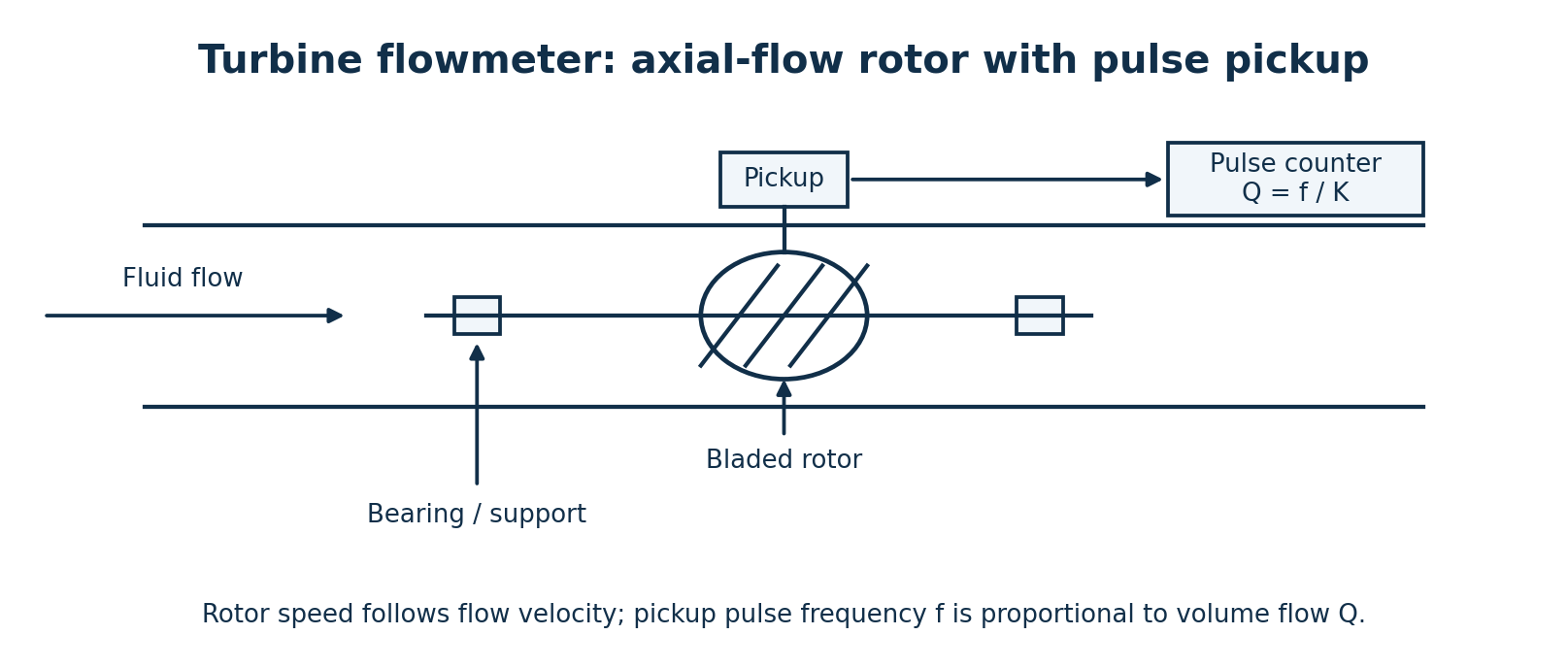
Fluid passing the angled rotor blades turns the rotor. Over the calibrated range, rotor speed is approximately proportional to mean fluid velocity. The pickup generates pulses as blades pass; pulse frequency f gives volume flow Q = f/K, and accumulated pulse count N gives volume V = N/K, where K is the calibrated pulses-per-unit-volume factor.
- It provides a pulse signal that is convenient for electronic rate indication and totalisation.
- It can provide good accuracy and repeatability for clean fluids within the calibrated flow and viscosity range.
Question 6(d)
A compressing force of 1250 N is applied to a steel rod of cross-sectional area 7 × 10⁻⁴ m². Determine the stress on the rod.
(2 marks)
Answer
| Step | Working |
|---|---|
| Definition | Compressive stress magnitude σ = F/A. |
| Substitute | σ = 1250/(7 × 10⁻⁴) = 1,785,714.286 N/m². |
| Answer | σ ≈ 1.786 MPa compressive; with tension taken as positive, the signed stress is −1.786 MPa. |
Question 7(a)
(i) Define the following terms with respect to strength of engineering materials: (I) stress; (II) strain. (ii) A loading force causes a material to deform by 0.02 mm. A strain sensor fitted on the material indicates the strain as 0.005. Determine the original length of the material.
(5 marks)
Answer
Stress is internal resisting force per unit area, measured in pascals. Engineering normal strain is the change in length divided by the original length, ε = ΔL/L₀; it is dimensionless.
| Step | Working |
|---|---|
| Rearrange | L₀ = ΔL/ε. |
| Use consistent units | ΔL = 0.02 mm; ε = 0.005 (not 0.005%). |
| Answer | L₀ = 0.02/0.005 = 4 mm = 0.004 m. |
Question 7(b)
Differentiate between active and passive transducers, citing one example of each.
(4 marks)
Answer
| Transducer | Meaning | Example |
|---|---|---|
| Active, in the self-generating instrumentation convention | Converts the measured physical energy to an electrical signal without a separate excitation supply for the sensing element. | Thermocouple generating a thermoelectric emf. |
| Passive | Requires excitation; the measurand changes resistance, inductance or capacitance, which a powered circuit converts to an output. | Resistance strain gauge excited in a Wheatstone bridge. |
The active/passive terminology differs in some electronics contexts. The self-generating versus externally excited convention is used here.
Question 7(c)
(i) State four advantages of natural piezoelectric crystals over synthetic crystals. (ii) Explain the piezoelectric effect.
(8 marks)
Answer
The comparison depends on the materials. A defensible interpretation is quartz, a naturally occurring piezoelectric material, compared with a typical poled ferroelectric ceramic. It is not valid to claim all natural crystals outperform all synthetic materials; synthetic quartz shares quartz’s properties.
- Quartz can offer excellent long-term stability.
- It does not depend on ferroelectric poling that can depolarise.
- Quartz has low dielectric losses.
- Quartz has no primary pyroelectric response, reducing charge caused directly by temperature change; thermal stresses can still cause measurement error.
Direct piezoelectric effect: applied mechanical stress redistributes charge within a suitable crystal and produces charge on its faces. For an appropriate mode, Q = dF. The converse effect is deformation when an electric field is applied. Electrodes and a suitable charge/voltage amplifier collect the signal.
Question 7(d)
(i) Define calibration with respect to measuring instrument. (ii) Highlight two reasons for regular calibration of strain gauge based meters.
(3 marks)
Answer
Calibration establishes the relationship between an instrument’s indications and corresponding reference values under specified conditions, including the relevant measurement uncertainty. Calibration is distinct from adjustment.
- Detect zero/sensitivity drift caused by ageing, temperature history, bonding changes or overload.
- Maintain reliable, traceable measurements and establish whether errors remain within the required tolerance.
Question 8(a)
State: (i) Three industrial applications of capacitive type displacement sensors. (ii) Two merits of capacitive type displacement sensors.
(5 marks)
Answer
- Measure small shaft displacement or vibration.
- Measure component thickness or dimensional gap.
- Measure precision stage position in machine or inspection systems.
- They can sense displacement without contact, avoiding mechanical wear and loading.
- They provide high sensitivity and resolution for small displacements when shielding, geometry and environment are controlled.
Question 8(b)
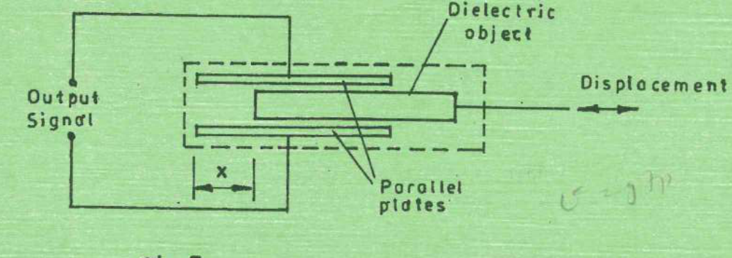
Figure 5 shows a push-pull capacitive displacement sensor. The relative permittivity of the dielectric object is 8 while dielectric constant of free space is 8.85 × 10⁻¹² F/m. The plates measures 5 cm × 0.4 cm and the separation distance is 4.8 cm. (i) Explain its operation; (ii) If the displacement x is 0.2 cm, determine the output capacitance in picofarads.
(9 marks)
Answer
Moving a dielectric changes the amount of dielectric between the plates and hence the capacitance. The printed drawing shows a sliding dielectric within a two-plate capacitor, although the text calls it “push-pull”. It does not show the three plates or two opposed capacitances required to calculate a differential three-plate output. The calculation below follows the displayed sliding-dielectric geometry.
| Step | Working |
|---|---|
| Geometry and stated assumption | Let L = 0.05 m be the plate length along movement, w = 0.004 m the width, d = 0.048 m the stated plate gap, and x = 0.002 m the air-filled length labelled at the left of the drawing. Assume the slab fills the gap over length L−x and neglect fringing. |
| Parallel areas | Air area A_air = wx; dielectric area A_d = w(L−x). Both areas share the same plate voltage, so their capacitances add. |
| Equation | C = ε₀A_air/d + ε₀εᵣA_d/d = ε₀w[x + εᵣ(L−x)]/d. |
| Substitution | C = (8.85 × 10⁻¹² × 0.004/0.048)[0.002 + 8(0.05−0.002)]. |
| Answer for the labelled air gap | C = 2.84675 × 10⁻¹³ F = 0.284675 pF. |
| Change from fully inserted dielectric | C_full = ε₀εᵣwL/d = 0.295 pF; ΔC = 0.284675−0.295 = −0.010325 pF. |
| Alternative interpretation, stated separately | If x instead means the inserted dielectric length, C = ε₀w[(L−x)+εᵣx]/d = 0.0472 pF. The drawing’s x label and displacement reference must be clarified before choosing that interpretation. |
No unit is silently changed: the printed plate separation of 4.8 cm is retained. The ideal parallel-plate calculation may be inaccurate for this unusual gap relative to the plate width because fringing can be significant.
Question 8(c)
Differentiate between contact and non-contact methods of data acquisition by tachometers.
(2 marks)
Answer
A contact tachometer places a spindle, wheel or coupling against the rotating shaft and mechanically follows its motion. A non-contact tachometer observes optical marks, magnetic teeth or another field signal without touching the shaft, reducing mechanical loading and wear.
Question 8(d)
Table 3 shows physical variables, their SI units and symbols. Complete the table.
| Physical variable | SI unit | Symbol |
|---|---|---|
| Torque | τ | |
| Angular velocity | rad/s | |
| Displacement | Δs | |
| Stress | N/m² |
(4 marks)
Answer
| Physical variable | SI unit | Conventional variable symbol |
|---|---|---|
| Torque | newton metre (N·m) | τ, or T |
| Angular velocity | radian per second (rad/s) | ω |
| Displacement | metre (m) | Δs, x or s, as defined |
| Stress | pascal (Pa = N/m²) | σ for normal stress; τ for shear stress |
A variable symbol is different from a unit symbol. Torque has the same base-unit dimensions as energy, but torque is written N·m rather than joule.