Plant Control Systems and Automation — October/November 2023
KNEC Diploma in Mechanical Engineering — Module III. Paper code: 2502/302. Time: 3 hours.
Questions are transcribed from the supplied examination paper. The independent revision answers are not official KNEC marking schemes. All eight questions, including optional questions, are answered.
Plant option. Answer any FIVE of the EIGHT questions. Maximum marks for each part of a question are as indicated.
The original block-diagram feedback signs, unloaded network output and PLC contact types are retained. Signed accelerometer coordinates, position-resolution conventions and assembly-literal radix are stated beside the working.
Question 1(a)
(i) Define control system with reference to plant automation. (ii) List four components of open loop control systems.
(5 marks)
Answer
A control system is an arrangement of connected elements that directs or regulates a plant process to achieve a specified output.
- Reference/input command.
- Controller or control unit.
- Actuator/final control element.
- Plant or process producing the output.
In an open-loop arrangement, the measured process output is not fed back to correct the command.
Question 1(b)
A heating control system is used to regulate the temperature of a room. The room has ventilation vents. (i) Draw a block diagram representation of the control system. (ii) Describe its operation.
(9 marks)
Answer
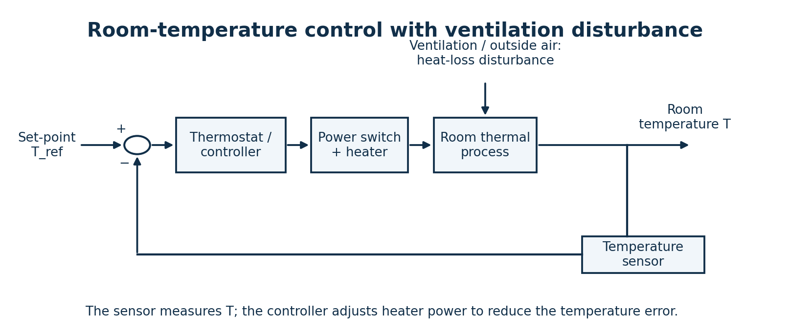
- Set the desired room temperature T_ref; measure the actual room temperature T with a sensor.
- Compare the feedback temperature with the set-point: e = T_ref − T.
- When the room is too cold, the thermostat/controller increases heater output or switches the heater on. When the upper switching threshold is reached, it reduces output or switches the heater off.
- Ventilation exchanges room air with outside air and changes heat loss; it enters as a disturbance to the room thermal process.
- Negative feedback detects the resulting temperature change and adjusts heating. A practical on/off thermostat uses hysteresis to avoid rapid switching.
Question 1(c)
Classify the following as open-loop or closed-loop control system; stating the reason in each case: (i) room air conditioner; (ii) electric hand drier; (iii) automatic washing machine.
(6 marks)
Answer
| System | Classification | Reason / stated assumption |
|---|---|---|
| Room air conditioner | Closed-loop, for thermostatic temperature regulation. | A room-temperature sensor feeds back the actual temperature and controls cooling relative to a set-point. |
| Electric hand drier | Open-loop with respect to hand dryness, for a timed or hand-presence-operated drier. | The drier does not measure whether the hands have reached a target dryness. Hand detection alone is not dryness feedback. |
| Automatic washing machine | Open-loop for the basic timed washing sequence. | A timer advances operations without measuring the cleanliness of the clothes. Modern machines can contain closed-loop water-level, temperature and motor-speed subsystems. |
Classification must name the controlled variable. Automation or the mere presence of a sensor does not by itself prove closed-loop regulation of the intended output.
Question 2(a)
(i) State three merits of open-loop control systems. (ii) Differentiate between manual and automatic control techniques with respect to closed loop control system.
(5 marks)
Answer
- Simple construction and straightforward operation.
- Lower cost because output sensing and feedback hardware can be omitted.
- No instability caused by an added feedback loop, although the plant itself still has to be stable.
In manual closed-loop control, a person observes the measured output, compares it with the target and adjusts the control input. In automatic closed-loop control, the sensor, comparator and controller perform that feedback correction without continuous human adjustment. Both are closed-loop when the output information is used to correct the input.
Question 2(b)
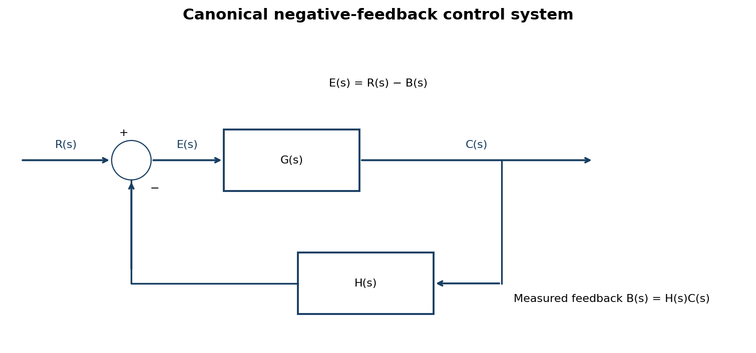
With the aid of a block diagram of a canonical control system, derive the expression for its transfer function.
(7 marks)
Answer
| Step | Working |
|---|---|
| Feedback signal | B(s) = H(s)C(s). |
| Error at the negative comparator | E(s) = R(s) − B(s) = R(s) − H(s)C(s). |
| Forward relation | C(s) = G(s)E(s) = G(s)[R(s)−H(s)C(s)]. |
| Collect output terms | [1+G(s)H(s)]C(s) = G(s)R(s). |
| Answer | C(s)/R(s) = G(s)/[1+G(s)H(s)], for zero initial conditions. |
For a positive-feedback comparator the corresponding denominator is 1−GH. The feedback sign must be read from the diagram.
Question 2(c)
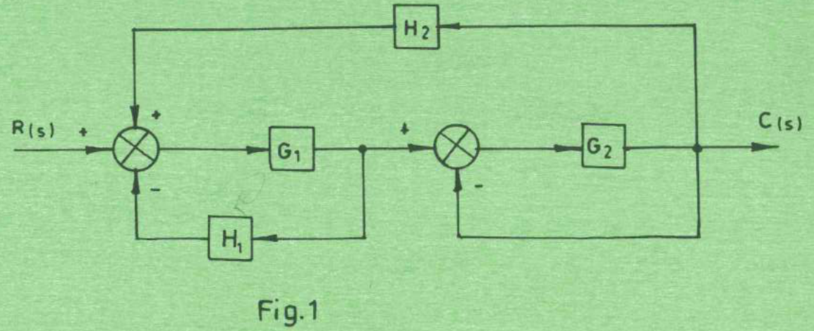
Figure 1 shows a block diagram of a control system. Determine its: (i) canonical form representation; (ii) overall transfer function.
(8 marks)
Answer
| Step | Working |
|---|---|
| Read the signs | The H₁ feedback enters the first junction negatively. H₂ enters that junction positively. The output C feeds back negatively at the second junction. |
| Name the intermediate signal | Let V be the output of G₁. Then V = G₁[R + H₂C − H₁V], so V = [G₁/(1+G₁H₁)]R + [G₁H₂/(1+G₁H₁)]C. |
| Close the local G₂ loop | C = G₂(V−C), hence C/V = G₂/(1+G₂). |
| Canonical positive outer loop | Use forward block G_eq = G₁G₂/[(1+G₁H₁)(1+G₂)] and positive feedback H_eq = H₂. |
| Canonical equation | C/R = G_eq/(1−G_eqH₂). |
| Answer | C(s)/R(s) = G₁G₂ / [(1+G₁H₁)(1+G₂)−G₁G₂H₂]. |
| Expanded denominator | 1 + G₂ + G₁H₁ + G₁G₂H₁ − G₁G₂H₂. |
Question 3(a)
(i) Explain the need for control system modelling. (ii) Outline the steps involved in control systems modelling.
(6 marks)
Answer
A model represents the relationships between system inputs, states and outputs. It enables prediction of response and stability, comparison of controller choices, and testing of designs before physical implementation.
- Define the control objective, system boundary, input, output and disturbances.
- Choose physical assumptions and a suitable level of detail; identify parameters.
- Apply relevant physical laws, such as force balance, energy balance or Kirchhoff’s laws, to derive equations.
- Linearise about a stated operating point when appropriate, then obtain a transfer-function or state-space representation.
- Estimate/measure parameters and compare model predictions with observed behaviour; revise the model if it is inadequate.
Question 3(b)
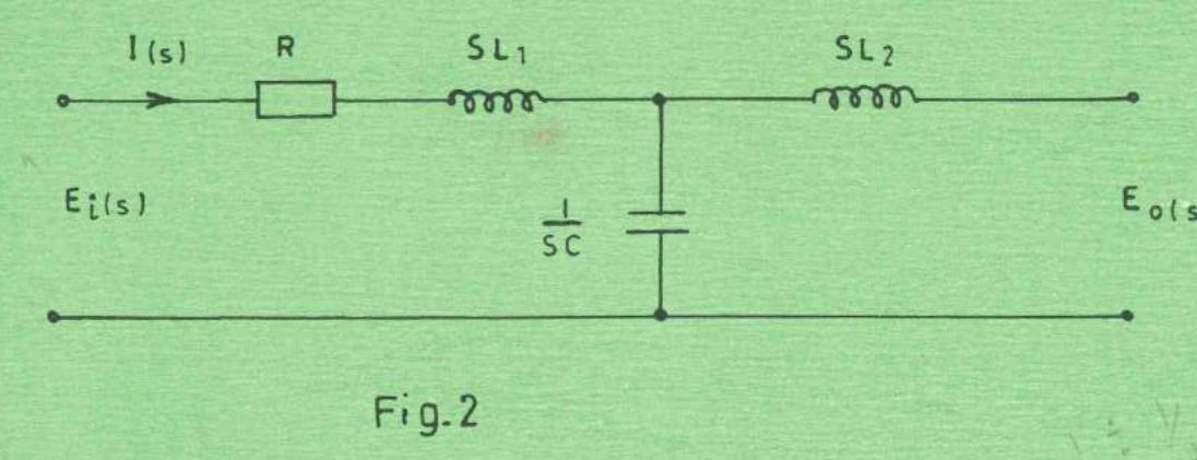
Figure 2 shows an electric network model of a control system. Determine the expression for the transfer function, Eₒ(s)/Eᵢ(s).
(6 marks)
Answer
| Step | Working |
|---|---|
| Read the drawn output condition | No output load is connected. For an ideal unloaded output, the current through L₂ is zero; its voltage drop is therefore zero. Eₒ equals the capacitor-node voltage. |
| Impedances | Z_series = R+sL₁; Z_C = 1/(sC). |
| Voltage divider | Eₒ/Eᵢ = Z_C/(Z_series+Z_C). |
| Simplify | Eₒ/Eᵢ = [1/(sC)]/[R+sL₁+1/(sC)]. |
| Answer for the unloaded network | Eₒ(s)/Eᵢ(s) = 1/(L₁Cs²+RCs+1). L₂ does not appear under the drawn open-circuit condition. |
| If an output load is intended | For load Z_L, define Z_p = [1/(sC)] ∥ (sL₂+Z_L). Then Eₒ/Eᵢ = [Z_p/(R+sL₁+Z_p)]·[Z_L/(sL₂+Z_L)]. A loaded numerical/symbolic result needs Z_L to be specified. |
Question 3(c)
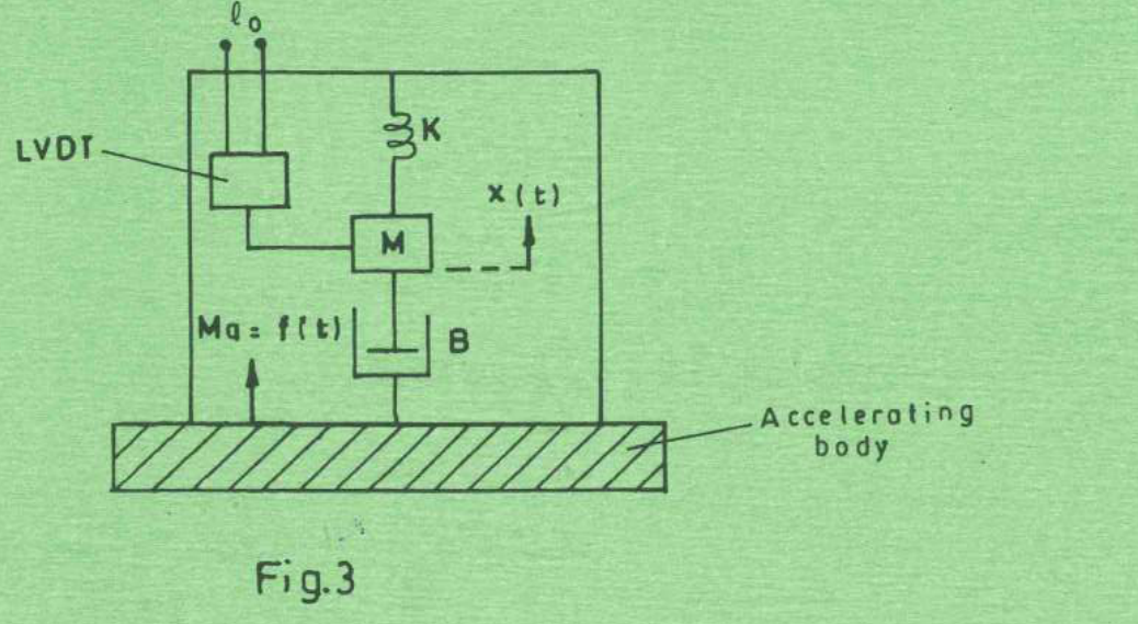
Figure 3 shows a mechanical system model of an accelerometer. (i) Write the differential equation for the system. (ii) Determine the transfer function, X(s)/A(s). (iii) If Eₒ(s) = K₁X(s), where K₁ is proportionality constant of LVDT, determine the expression, Eₒ(s)/A(s).
(8 marks)
Answer
Define y(t) as housing displacement, z(t) as the absolute mass displacement, a(t) = d²y/dt², and x(t) = z(t)−y(t) as mass displacement relative to the housing, measured in the same positive direction. Work about static equilibrium so gravity is already balanced.
| Step | Working |
|---|---|
| Force balance on the mass | M d²z/dt² = −B(dx/dt)−Kx. |
| Substitute z=x+y | M d²x/dt² + B dx/dt + Kx = −Ma(t). |
| Transform with zero initial conditions | (Ms²+Bs+K)X(s) = −MA(s). |
| Answer (ii), defined signed displacement | X(s)/A(s) = −M/(Ms²+Bs+K). |
| Answer (iii) | Eₒ(s)/A(s) = −K₁M/(Ms²+Bs+K). |
| Opposite deflection convention | If x is instead defined in the direction of inertial deflection, x=y−z, the right-hand side is +Ma and both transfer functions are positive. The magnitude is unchanged. |
The sign is a coordinate convention, not a change in the accelerometer dynamics. For frequencies well below √(K/M), the magnitude approaches M/K and the output is approximately proportional to acceleration.
Question 4(a)
State four merits of d.c. servomotors.
(4 marks)
Answer
- High available starting torque for a suitable motor and drive.
- Motor torque is approximately proportional to armature current when field flux is held constant.
- Convenient speed control over a useful range by controlling the armature supply.
- Rapid controlled acceleration, deceleration and reversal in low-inertia servo designs.
Question 4(b)
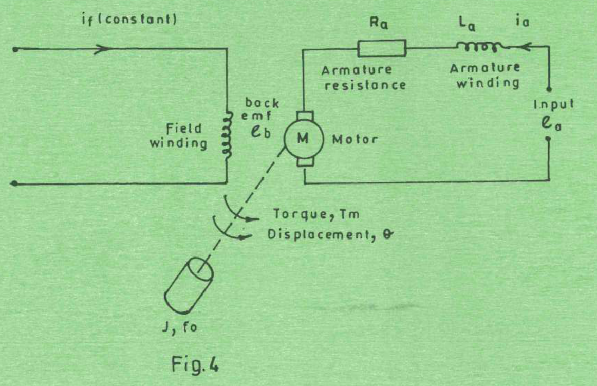
Figure 4 shows an equivalent circuit of armature controlled d.c. servomotor. (i) Write the differential equation for the: I. armature circuit input, eₐ; II. torque, Tₘ. (ii) Determine the laplace transform for the equations in b(i).
(8 marks)
Answer
| Step | Working |
|---|---|
| Define constants | Armature resistance Rₐ, inductance Lₐ, inertia J, viscous coefficient f₀, torque constant Kₜ and back-emf constant K_b; field current is constant. |
| Armature input equation | eₐ(t) = Lₐ diₐ/dt + Rₐiₐ(t) + e_b(t), where e_b = K_b dθ/dt. |
| Torque equation | Tₘ(t) = Kₜiₐ(t) = J d²θ/dt² + f₀ dθ/dt, neglecting external load torque as in the shown model. |
| Armature transform | Eₐ(s) = (Lₐs+Rₐ)Iₐ(s) + K_b sΘ(s), for zero initial conditions. |
| Torque transform | Tₘ(s) = KₜIₐ(s) = (Js²+f₀s)Θ(s). |
| If load torque is present | Add T_L(t) to the mechanical right-hand side: Tₘ = Jθ̈+f₀θ̇+T_L. The torque constant relation Tₘ=Kₜiₐ still holds. |
Question 4(c)
(i) Draw a labelled diagram of a double-acting cylinder connected to a 4/3 spool control valve. (ii) Describe the operation of the set-up in (c)(i).
(8 marks)
Answer
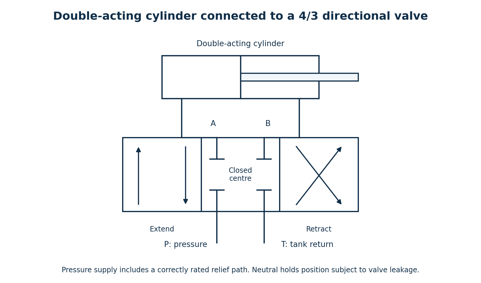
- In the extend position, P connects to A and B connects to T. Pressure acts on the cap end and the rod extends; displaced rod-end fluid returns to tank.
- In the retract position, P connects to B and A connects to T. Pressure acts on the rod end and the rod retracts.
- For the closed-centre valve illustrated, the neutral position blocks P, T, A and B, tending to hold the cylinder position, subject to leakage.
- The pressure source needs an appropriate relief/unloading arrangement. Other 4/3 centre configurations are possible; their neutral behaviour must be stated separately.
Question 5(a)
Differentiate between each of the following with respect to process control: (i) step input and transient state; (ii) set-point and controlled variable.
(4 marks)
Answer
| Pair | First term | Second term |
|---|---|---|
| (i) | A step input is an abrupt change from one constant input level to another at a specified time. | The transient state is the period of changing system response after an input or disturbance change, before steady behaviour is reached. |
| (ii) | The set-point is the desired target value. | The controlled variable is the actual process quantity being regulated. |
Question 5(b)
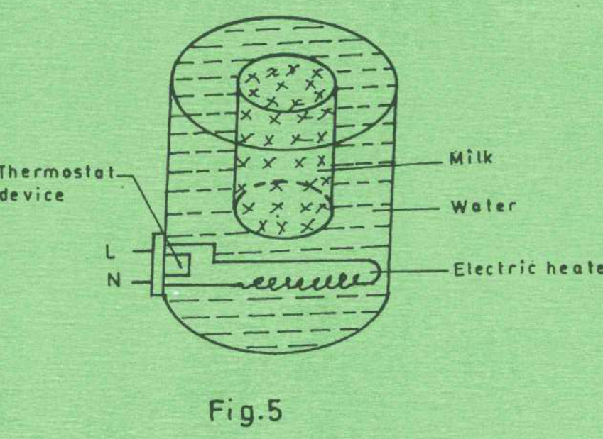
Figure 5 shows a milk heating process. It is desired to maintain the milk temperature at 60° C. Identify the following: (i) set-point; (ii) manipulated variable; (iii) controlled variable; (iv) final control element; (v) feedback element.
(5 marks)
Answer
| Element | Identification |
|---|---|
| (i) Set-point | Desired milk temperature: 60 °C. |
| (ii) Manipulated variable | Electrical heating power supplied to the water bath. |
| (iii) Controlled variable | Milk temperature, as stated in the question. |
| (iv) Final control element | The heater power-switching contact/relay operated by the thermostat; the immersion heater converts that controlled electrical power to heat. |
| (v) Feedback element | The thermostat’s temperature-sensing element. |
The printed sensor appears in the water jacket. As drawn, it directly senses bath temperature, which is only a proxy for milk temperature. Directly maintaining milk at 60 °C would require milk-temperature feedback or a validated relationship and suitable bath setting; the two temperatures are not automatically identical.
Question 5(c)
Figure 6 shows an analogue controller. Determine the: (i) proportional gain, kp; (ii) output voltage, Vₒ.
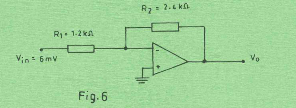
(4 marks)
Answer
| Step | Working |
|---|---|
| Read Figure 6 | R₁ = 1.2 kΩ, R₂ = 2.4 kΩ and V_in = 6 mV. The non-inverting input is grounded. |
| Ideal inverting amplifier | Vₒ/V_in = −R₂/R₁. |
| Proportional gain | The signed circuit gain is −2. The positive proportional-gain magnitude k_p = R₂/R₁ = 2. |
| Output | Vₒ = −(2.4/1.2) × 6 mV = −12 mV = −0.012 V. |
Question 5(d)
(i) Draw a labelled circuit diagram of operational amplifier based proportional Plus Integral plus Derivative (PID) controller. (ii) Write the expression for each of the following with respect to the PID controller in d(i): I. proportional gain, Kp; II. integral gain, Ki; III. derivative gain, Kd.
(7 marks)
Answer
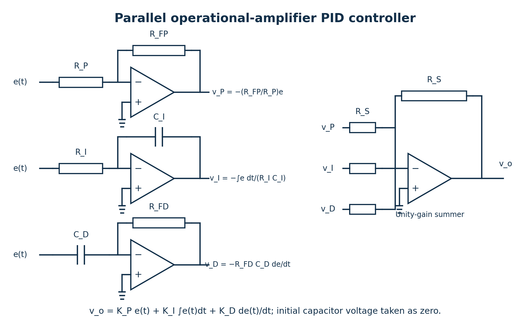
| Term | Branch output | Gain after the final unity-gain summer |
|---|---|---|
| Proportional | v_P = −(R_FP/R_P)e | Kp = R_FP/R_P. |
| Integral | v_I = −∫e dt/(R_I C_I), for zero initial capacitor voltage | Ki = 1/(R_I C_I), in s⁻¹. |
| Derivative | v_D = −R_FD C_D de/dt | Kd = R_FD C_D, in s. |
The final summer gives vₒ = Kp e + Ki∫e dt + Kd de/dt. These are the gains of the illustrated parallel form. In the alternative ideal form Kp[e + (1/Ti)∫e dt + Td de/dt], Ki = Kp/Ti and Kd = KpTd. Practical circuits limit differentiator bandwidth and integrator saturation.
Question 6(a)
State four merits of industrial robots.
(4 marks)
Answer
- Repeatable execution of programmed operations with consistent quality.
- High productivity on suitable repetitive tasks.
- Removal of people from hazardous or unpleasant operations.
- Reprogrammability for different products or task sequences, within the robot’s physical capabilities.
Question 6(b)
Describe each of the following with respect to robot performance: (i) work envelope; (ii) degree of freedom; (iii) speed of movement.
(6 marks)
Answer
- Work envelope: the region of space the robot’s end effector can reach, subject to joint limits, geometry and tool configuration.
- Degree of freedom: an independent joint or coordinate of motion needed to describe the robot configuration, such as a rotary or linear axis.
- Speed of movement: the rate of joint or end-effector motion, stated in units such as degrees/s, rad/s or mm/s and subject to payload, acceleration and path limits.
Question 6(c)
The arm of an industrial robot obtains a total range of rotation of 160°. The arm fully extends to 1500 mm and fully retracts to 750 mm from the pivot joint. The robot has 10-bit memory. Determine the: (i) control resolution of rotation; (ii) control resolution of translation.
(6 marks)
Answer
Interpret “10-bit memory” as a 10-bit position command/encoding for each axis. A memory-capacity statement by itself would not define position resolution. For N discrete endpoint-inclusive positions, there are N−1 intervals.
| Step | Working |
|---|---|
| Position levels | N = 2¹⁰ = 1024 positions. |
| (i) Rotation range | θ_max−θ_min = 160°. |
| Rotational resolution | Δθ = 160/(1024−1) = 0.1564027° per interval. |
| (ii) Translation range | r_max−r_min = 1500−750 = 750 mm. |
| Translation resolution | Δr = 750/(1024−1) = 0.7331378 mm per interval. |
| Alternative bin-width convention | If the range is divided into 1024 quantisation bins instead, the nominal widths are 160/1024 = 0.15625° and 750/1024 = 0.732421875 mm. State the convention. |
Resolution describes the command increment. It is not a guarantee of mechanical accuracy or repeatability.
Question 6(d)
Explain each of the following with respect to robots: (i) tactile sensing; (ii) vision.
(4 marks)
Answer
- Tactile sensing detects contact-related information, such as touch, pressure, force distribution or slip at a gripper. The controller can use it to regulate grasping or confirm contact.
- Vision uses cameras and image processing to identify, locate or inspect objects and guide robot action. Calibration relates image information to the robot/workspace coordinates.
Question 7(a)
State: (i) two features of SCADA software; (ii) three types of communication system in a SCADA system.
(5 marks)
Answer
- Real-time graphical monitoring and supervisory display of process variables.
- Alarm/event handling and historical data logging/trending.
- Wired serial or industrial communication links, such as RS-485-based systems.
- Wired Ethernet/IP networks, including suitable fibre links.
- Wireless communication links, such as licensed radio or cellular telemetry.
The communication categories describe the medium/network; the application protocol and reliability requirements must also be selected.
Question 7(b)
Figure 7 shows a Programmable Logic Controller (PLC) ladder diagram program. (i) Describe the control operation; (ii) Write the equivalent instruction listing program.
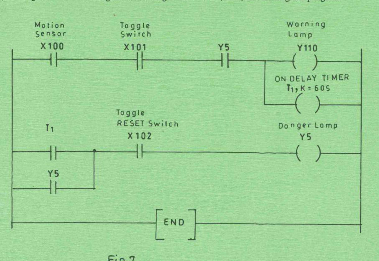
(10 marks)
Answer
Read the contacts exactly as printed. In the first rung X100, X101 and Y5 are all drawn as normally open logic contacts. Y110 and the 60-second on-delay timer T₁ are parallel outputs. In the second rung the T₁ contact is in parallel with Y5, followed by X102 and output coil Y5.
| Step | Working |
|---|---|
| Printed first-rung logic | W = X100 AND X101 AND Y5. Then Y110 = W, and W enables the non-retentive on-delay timer T₁ with preset 60 s. |
| Printed second-rung logic | Y5_new = (T₁_done OR Y5_previous) AND X102. The Y5 branch is a seal-in path. |
| Initial off-state check | With Y5 = 0 and T₁_done = 0, W = 0. The timer cannot start, so Y5 remains 0 even if X100, X101 and X102 are all 1. The warning/danger sequence cannot initiate from this normal reset state. |
| Reset behaviour as printed | Setting X102 to 0 breaks the seal-in expression and switches Y5 off. On the following scan the first rung becomes false and a non-retentive timer resets. X102 is not drawn as an inverted software contact. |
Equivalent generic instruction listing for the printed circuit (the exact timer mnemonic and time-base encoding depend on the PLC):
LD   X100
AND  X101
AND  Y5
OUT  Y110
TON  T1, T#60s
LD   T1
OR   Y5
AND  X102
OUT  Y5
END
Conditional intended sequence: if the first-rung Y5 contact was intended to be normally closed, replace only that AND Y5 by AND NOT Y5 (often ANI Y5). With X102 = 1 as the healthy/reset-permissive state, motion and the enabled toggle then start Y110 and T₁. At 60 s, T₁ sets and seals Y5, the danger lamp comes on, and the inverted Y5 contact turns the warning lamp/timer off on the next scan. Opening the X102 permissive resets the latch. This is an explicitly corrected interpretation, not the circuit as printed.
Question 7(c)
(i) Draw a PLC ladder symbol for NC coil. (ii) Describe the following states of coil of a PLC output relay: I. NC state; II. NO state.
(5 marks)
Answer
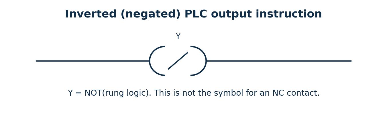
The paper uses “NC coil”. Strictly, a physical relay coil is energised or de-energised; normally closed and normally open describe its contacts. A negated software coil is commonly drawn as a coil symbol with a slash and sets Y = NOT(rung result). It must be distinguished from an NC contact instruction.
| Physical relay contact | Coil de-energised | Coil energised |
|---|---|---|
| Normally closed (NC) | Closed, so its contact path conducts. | Opens. |
| Normally open (NO) | Open, so its contact path does not conduct. | Closes. |
The normal state refers to the unoperated relay. A software contact tests a bit; its symbol alone does not specify how a field switch is physically wired.
Question 8(a)
Define each of the following 8051 micro controller registers: (i) stack pointer; (ii) data pointer; (iii) program counter.
(3 marks)
Answer
- Stack pointer (SP): the 8-bit register identifying the current internal-RAM stack top; PUSH/CALL increment it before storing.
- Data pointer (DPTR): the 16-bit address register formed from DPH and DPL, used for indexed/external-memory addressing.
- Program counter (PC): the 16-bit register holding the address used for instruction sequencing in program memory.
Question 8(b)
Describe each of the following elements of 8051 micro controller internal architecture: (i) Central Processing Unit (CPU); (ii) Read Only Memory (ROM).
(6 marks)
Answer
- CPU: fetches and decodes instructions, performs arithmetic/logic operations and controls data movement and peripheral activity. Its working elements include the ALU, registers and instruction-control circuitry.
- ROM: non-volatile program storage read during execution. The original 8051 includes 4 KB on-chip program ROM; other family members have different code-memory sizes or technologies. Program memory is logically distinct from data memory.
Question 8(c)
State the special function of each of the following I/O pins of port 3 in 8051 micro controller: (i) RXD; (ii) INT̅₀; (iii) T₀; (iv) W̅R̅; (v) R̅D̅.
(5 marks)
Answer
| Function | Port pin | Special function |
|---|---|---|
| RXD | P3.0 | Serial receive input. |
| INT₀ (active low) | P3.2 | External interrupt 0 input. |
| T₀ | P3.4 | Timer/counter 0 external input. |
| WR (active low) | P3.6 | External data-memory write strobe. |
| RD (active low) | P3.7 | External data-memory read strobe. |
Question 8(d)
Explain what the following 8051 Instructions accomplishes, stating the machine Hexadecimal code of each: (i) MOV A, 50 H; (ii) ADD A, @R0; (iii) MOV A, #47.
(6 marks)
Answer
| Instruction | Operation | Hexadecimal machine bytes |
|---|---|---|
| MOV A, 50 H | Direct addressing: load A with the byte stored at internal RAM address 50H. This does not load the literal value 50H. | E5 50 |
| ADD A, @R0 | Register-indirect addressing: add the internal-RAM byte addressed by R0 to A; store the 8-bit result in A. ADD updates arithmetic flags; it does not include carry-in. | 26 |
| MOV A, #47 | Immediate addressing: load decimal 47 into A, with the usual default decimal interpretation of an unsuffixed constant. 47 decimal = 2FH. | 74 2F |
Opcode lookup: E5 is MOV A,direct; 26 is ADD A,@R0; 74 is MOV A,#immediate. The operand byte follows where required. If an assembler’s radix is explicitly changed, the unsuffixed #47 depends on that setting. If the intended literal were #47H, the bytes would instead be 74 47; H is not printed in this third instruction.