Power Production Systems — October/November 2023
KNEC Diploma in Mechanical Engineering — Module III. Paper code: 2502/305. Time: 3 hours.
Questions are transcribed from the supplied examination paper. The independent revision answers are not official KNEC marking schemes. All 7 questions, including optional questions, are answered.
Plant option. Answer FIVE of the following SEVEN questions. Maximum marks for each part of a question are as indicated.
All seven printed questions are covered. Question 5(a) carries 9½ marks and 5(b) carries 4½ marks in the source. Maintenance and testing answers are examination outlines; equipment-specific settings are not supplied in this paper.
Question 1(a)
Define the following terms in relation to steam: (i) wet; (ii) superheated; (iii) dryness fraction.
(3 marks)
Answer
- Wet steam: a mixture of saturated water vapour and suspended liquid water at the saturation condition.
- Superheated steam: vapour at a temperature above the saturation temperature corresponding to its pressure.
- Dryness fraction: the mass fraction of vapour in a wet mixture, x = m_vapour/(m_vapour+m_liquid). It lies between 0 and 1 and is not a quality variable for superheated steam.
Question 1(b)
With the aid of a sketch, explain the construction and operation of a throttling calorimeter.
(7 marks)
Answer
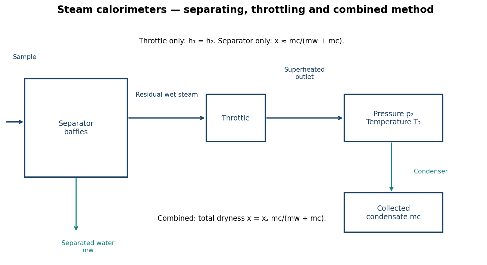
- Construction: a representative steam-sampling connection leads to an insulated chamber and a small throttling orifice/valve. Pressure is measured upstream; downstream pressure and temperature are measured before safe discharge/condensation.
- A small steam sample passes through the restriction from p₁ to a lower p₂. With negligible heat transfer, shaft work and kinetic/potential-energy changes, throttling is approximately isenthalpic: h₁ = h₂.
- Choose the pressure reduction so that the downstream sample is superheated. Determine h₂ from its measured p₂ and T₂ using steam tables.
- Upstream wet-steam enthalpy is h₁ = h_f(p₁)+x h_fg(p₁). Hence x = [h₂−h_f(p₁)]/h_fg(p₁).
- If the downstream state remains wet, p₂ and T₂ do not determine enthalpy uniquely. A throttling-only calorimeter then cannot determine the original dryness; a separating-and-throttling arrangement or another method is required.
Question 1(c)
With the aid of sketches, explain the constructional difference between induced draught and forced draught cooling towers.
(5 marks)
Answer
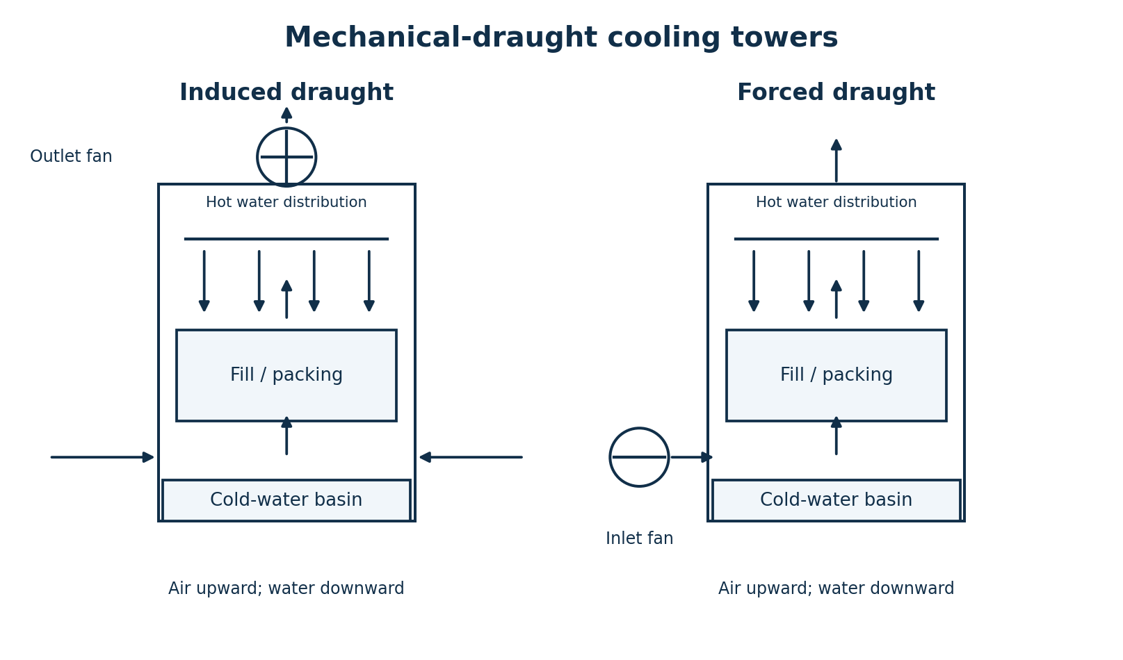
| Feature | Induced draught | Forced draught |
|---|---|---|
| Fan position | At/near the discharge at the top of the tower. | At the air inlet, commonly near the base or side. |
| Air movement | The fan draws air through the wetted fill and discharges warm moist air. | The fan pushes incoming air through the wetted fill toward the outlet. |
| Common construction | Water distribution, fill, drift eliminators and a cold-water basin are arranged in the air path. | The same heat-transfer components are used; the fan placement and inlet/outlet arrangement differ. |
The sketches use counterflow for a direct comparison. “Induced/forced draught” identifies the fan arrangement; it is distinct from “counterflow/crossflow”, which describes the relative air and water paths.
Question 1(d)
List five maintenance checks for each of the following: (i) surface condensor; (ii) cooling tower.
(5 marks)
Answer
| Surface condenser — five checks | Cooling tower — five checks |
|---|---|
| Inspect/clean tube surfaces for fouling and scale. | Inspect fill, spray nozzles and water distribution. |
| Check tube integrity and leakage between cooling water and condensate. | Check fan blades, bearings, drive/belts and alignment. |
| Check vacuum/air leakage and operation of air-removal equipment. | Clean basin/strainers and verify water levels and make-up controls. |
| Check cooling-water flow, inlet/outlet temperatures and pressure loss. | Check water-treatment condition, conductivity/blowdown and the site biological-control program. |
| Check condensate level, pumps, seals and condensate quality. | Inspect structure, drift eliminators, corrosion, leaks and vibration. |
These are inspection categories; maintenance requiring access follows isolation and the equipment procedure.
Question 2(a)
(i) With the aid of sketches, explain the cycle of operation of a four stroke spark ignition engine. (ii) Outline the procedure of determining indicated power by Morse test on a four cylinder petrol engine coupled to a dynamometer.
(16 marks)
Answer
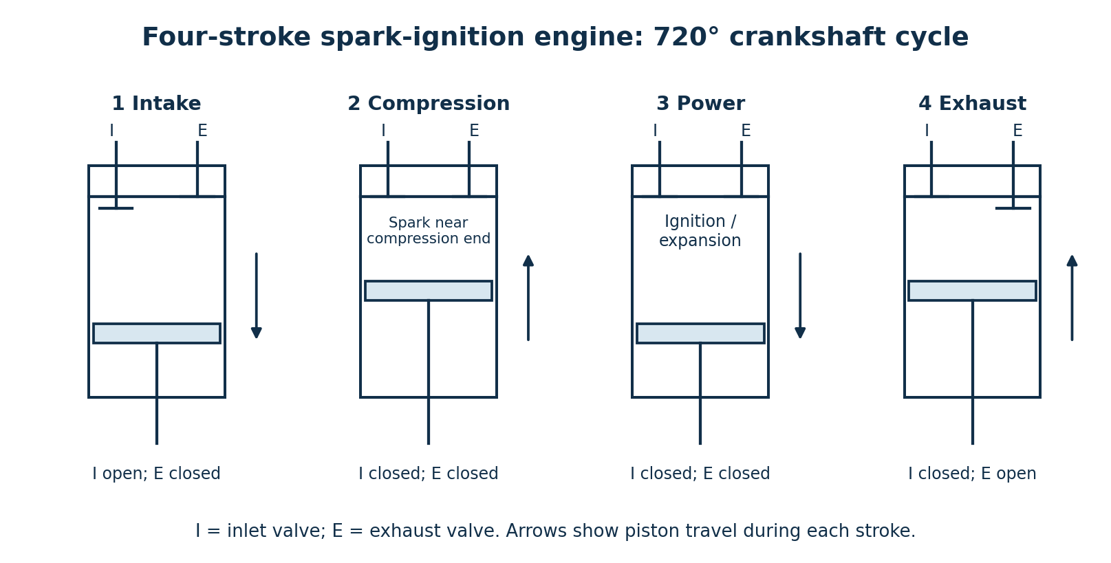
| Stroke | Piston motion | Valve condition and operation |
|---|---|---|
| Intake | TDC to BDC | Inlet open and exhaust closed in the idealised cycle. Fresh charge enters; in a conventional port-fuelled engine this is an air–fuel mixture. |
| Compression | BDC to TDC | Both valves closed. The charge is compressed; the spark is timed near the end of compression. |
| Power / expansion | TDC to BDC | Both valves closed for most of the stroke. Burning gases expand and do work on the piston. |
| Exhaust | BDC to TDC | Exhaust open and inlet closed in the idealised cycle. Burnt gases are expelled. |
One complete cycle requires two crankshaft revolutions, 720°. Real valve timing includes lead, lag and overlap.
- Warm the engine and stabilise it at the specified test speed with all four cylinders firing. Measure total brake power B with the dynamometer.
- Following the approved test method, disable combustion in cylinder 1. Reduce the dynamometer load to restore the same speed, keeping the other operating conditions as nearly unchanged as possible. Record brake power B₁ with that cylinder cut out.
- Restore cylinder 1 and allow conditions to stabilise. Repeat independently for cylinders 2, 3 and 4, recording B₂, B₃ and B₄ at the same speed.
- Assume total friction/pumping power is unchanged by each cut-out. The indicated power contributed by cylinder i is I_i = B−B_i.
- Add the four cylinder contributions: I_total = 4B−(B₁+B₂+B₃+B₄). If required, friction power F = I_total−B and mechanical efficiency η_m = B/I_total.
The Morse result is approximate because friction and pumping losses can change when a cylinder stops firing. No numerical power is asserted because the paper supplies no dynamometer readings.
Question 2(b)
Outline four advantages of nuclear power plants.
(4 marks)
Answer
- High energy output from a small mass of nuclear fuel.
- Low direct greenhouse-gas and combustion-air-pollutant emissions during generation.
- Ability to provide large, sustained power output when the plant is available.
- Generation is largely independent of short-term wind and sunlight conditions, with relatively infrequent fuel deliveries.
Question 3(a)
(i) With the aid of a diagram, explain the operation of a spreader stoker used in a boiler. (ii) State two advantages and two disadvantages of the stoker in (a)(i).
(8 marks)
Answer
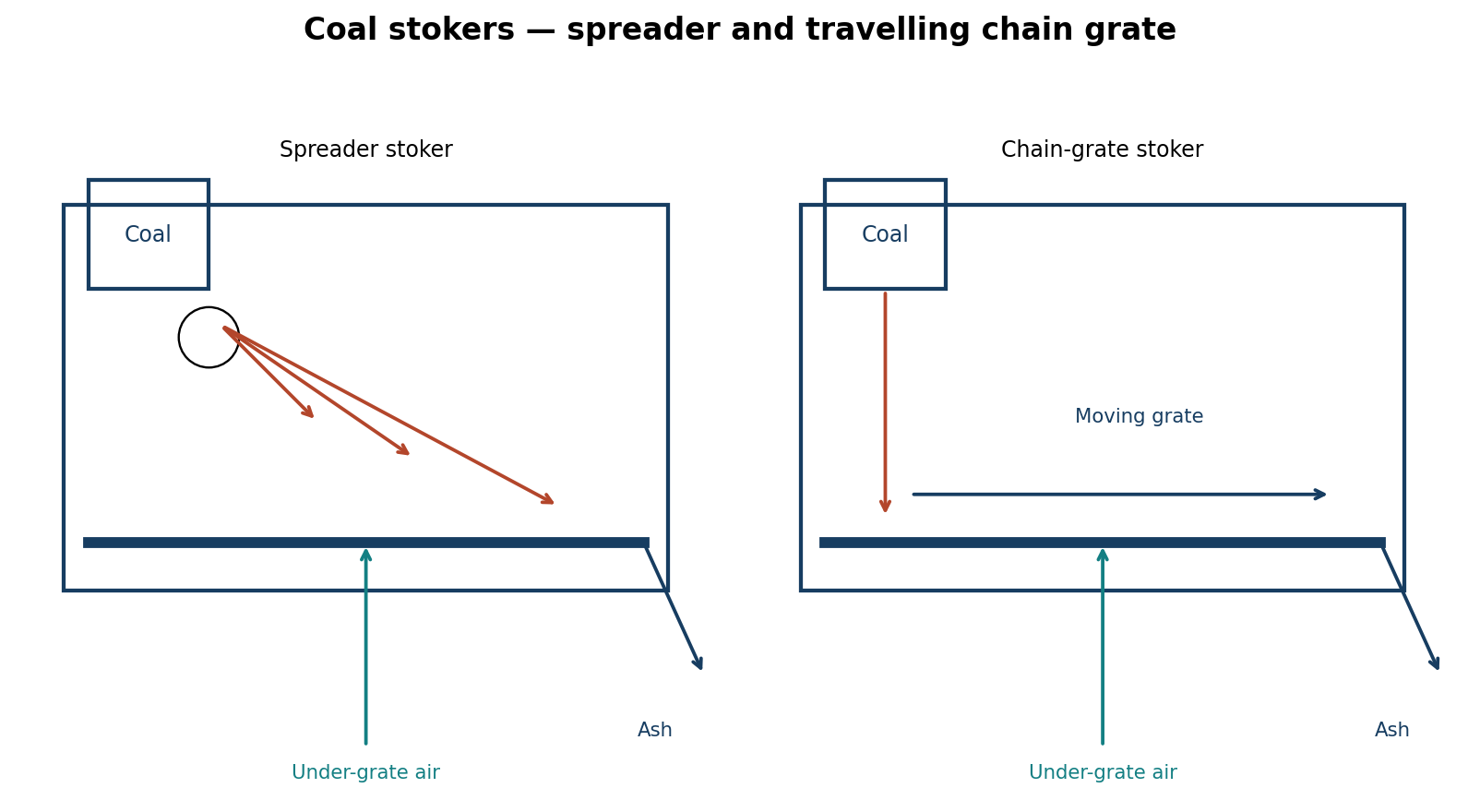
A feeder meters coal onto a rotating mechanical spreader or a suitable pneumatic distributor. Fuel is thrown across the furnace above the grate. Fine particles burn partly in suspension; larger particles land on the grate and finish burning in a relatively thin bed. Under-grate air supports bed combustion, and over-fire air can complete combustion above the bed. Ash is discharged from the grate arrangement.
| Two advantages | Two disadvantages |
|---|---|
| Rapid response to fuel-feed changes and boiler-load demand. | Fine-fuel carryover can increase fly ash and unburnt-carbon losses. |
| Reasonably uniform distribution and ability to burn a suitable range of solid-fuel particle sizes. | Distributor/grate wear and fuel-size/air-distribution control require maintenance and adjustment. |
Question 3(b)
Describe the following problems in boilers: (i) Scale formation. (ii) Corrosion; (iii) Priming.
(6 marks)
Answer
- Scale formation: hard adherent deposits build up on heat-transfer surfaces when dissolved salts precipitate. The insulating layer reduces heat transfer and can cause local overheating.
- Corrosion: chemical/electrochemical attack wastes boiler metal, for example from dissolved oxygen or unsuitable water chemistry, causing pitting, thinning or leakage.
- Priming: liquid boiler water is carried into the steam outlet as droplets, often during sudden demand changes, excessive water level or foaming. The resulting wet/contaminated steam can foul downstream equipment.
Question 3(c)
With the aid of diagrams, explain the operation of a bag filter plant in pollution control.
(6 marks)
Answer
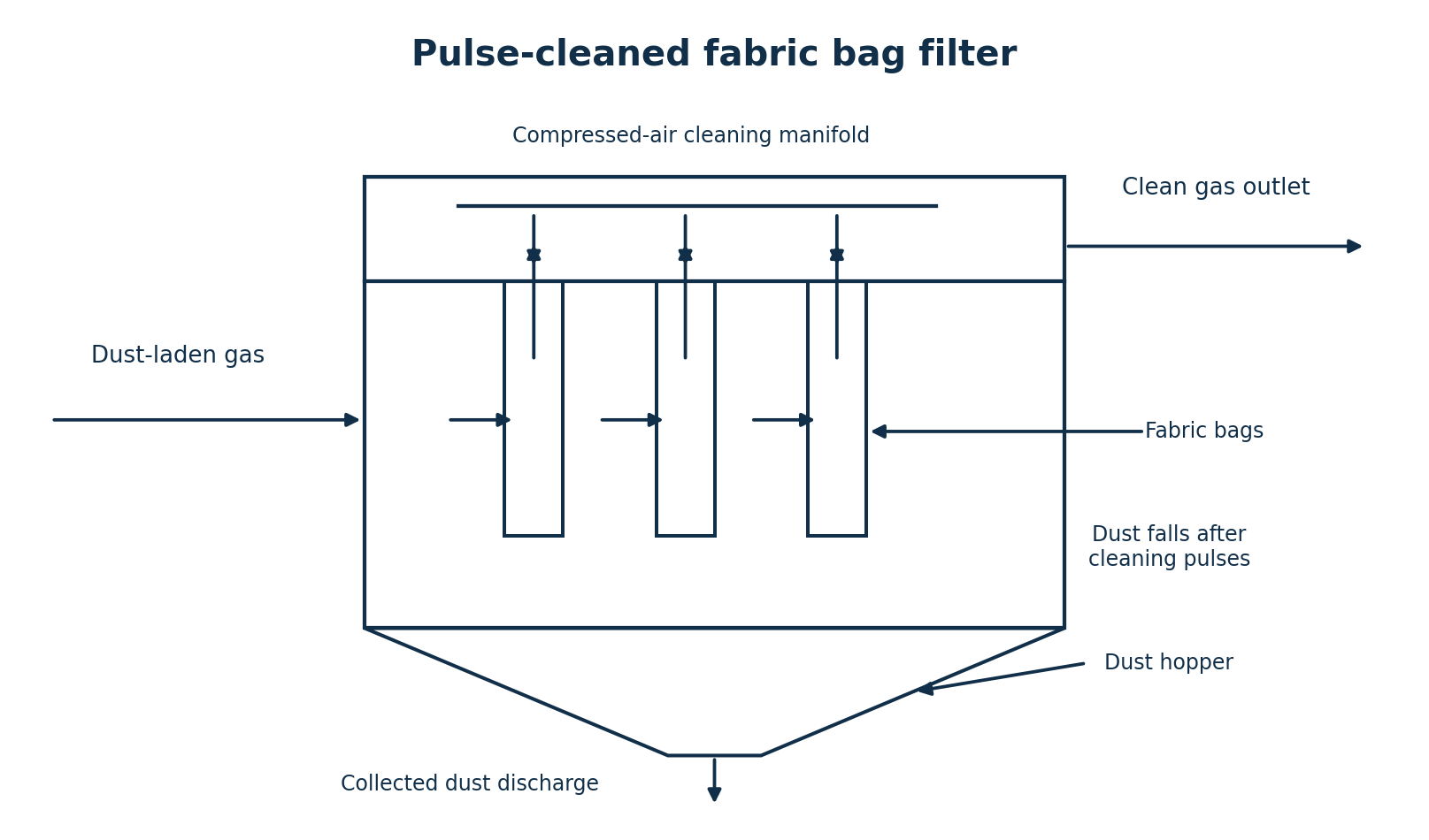
- Dust-laden gas enters the dirty chamber and is distributed around the fabric filter bags.
- Gas passes through the fabric and its accumulated dust cake; particles are retained on the dirty side.
- Filtered gas flows through the bag interiors into a clean-gas plenum and then to the outlet fan/stack.
- Periodic reverse-air, shaking or pulse-jet cleaning removes the dust cake. The illustrated design uses short compressed-air pulses.
- Dislodged dust falls into the hopper and leaves through a sealed discharge device. Monitor differential pressure and bag integrity to detect excessive loading or leakage.
Fabric selection and gas temperature must suit the process; this equipment removes particulate matter and does not by itself remove all gaseous pollutants.
Question 4(a)
(i) Explain the need for energy audit in industries. (ii) Describe the following types of energy audit: (I) preliminary; (II) comprehensive; (III) system specific.
(8 marks)
Answer
An energy audit identifies where and how energy is used, quantifies significant losses and develops justified improvement opportunities. It supports cost reduction, prioritisation of investment and verification of energy performance relative to production.
| Audit type | Description |
|---|---|
| Preliminary | A walk-through and review of bills/operating information to establish major energy uses and identify obvious low-cost opportunities and priorities for deeper investigation. |
| Comprehensive | A detailed plant assessment using measurements, energy balances and operating analysis to estimate savings, costs, feasibility and implementation priorities. |
| System specific | A focused investigation of one energy-using system, such as compressed air, boilers, refrigeration or motor drives, including its supply, distribution and end uses. |
Question 4(b)
Outline four elements of energy monitoring and targeting system.
(6 marks)
Answer
- Measure and record energy use and relevant drivers such as production, operating hours and weather.
- Analyse the data to establish a baseline and meaningful energy-performance indicators, accounting for changes in the drivers.
- Set realistic targets/budgets and compare actual performance with expected consumption.
- Report deviations, investigate causes, implement corrective actions and verify the resulting savings.
Question 4(c)
Explain the following steam distribution system problems and state two causes of each: (i) steam leakage; (ii) pipeline erosion; (iii) water hammer.
(6 marks)
Answer
| Problem | Explanation | Two causes |
|---|---|---|
| Steam leakage | Steam escapes through an unintended opening, wasting heat and water. | (1) Worn/damaged valve packing, gaskets or seals. (2) Corroded/cracked pipework or loosened joints. |
| Pipeline erosion | Material is mechanically removed from the pipe or fittings. | (1) High-velocity wet steam or entrained droplets. (2) Concentrated impingement at bends/restrictions or abrasive debris carried in the flow. |
| Water hammer | A pressure shock occurs when moving condensate is abruptly stopped or steam collapses rapidly in contact with colder condensate. | (1) Inadequate drainage/failed traps allow condensate pockets. (2) Rapid valve opening or poor pipe falls/pockets accelerate water or expose cold condensate to steam. |
Question 5(a)
(i) State four desired properties of a moderator in a nuclear plant. (ii) Outline five factors considered when selecting site for locating a nuclear power.
(9.5 marks)
Answer
- Good slowing-down ability: a large reduction in neutron energy per scattering collision, generally favoured by light nuclei.
- A high probability of neutron scattering.
- Low neutron absorption, so useful neutrons are not unnecessarily lost.
- Adequate thermal, radiation and chemical stability under reactor operating conditions.
| Five site factors | Reason |
|---|---|
| Cooling-water/heat-rejection availability | Provide the required cooling under credible seasonal conditions. |
| Geology and natural hazards | Assess seismic, flood, tsunami, landslide and other relevant site hazards. |
| Population and emergency-planning suitability | Allow protective arrangements and appropriate land use around the plant. |
| Environmental suitability | Assess effects on water, ecosystems and surrounding communities. |
| Infrastructure and electrical network | Provide grid connection, transport access and other essential support services. |
Question 5(b)
Outline three types of fuels used to generate nuclear power.
(4.5 marks)
Answer
| Fissile fuel isotope | Outline |
|---|---|
| Uranium-235 | A fissile component of uranium fuel used in many power reactors. |
| Plutonium-239 | A fissile component that can be used in suitable plutonium-containing or mixed-oxide (MOX) fuel. |
| Uranium-233 | A fissile isotope associated with thorium fuel cycles. |
If fuel families are named by element, distinguish uranium-based fuel, plutonium-containing fuel and thorium-based fuel cycles. Thorium-232 itself is fertile: it supports a cycle that produces fissile uranium-233 and is not interchangeable with a directly fissile fuel. Likewise uranium-238 is fertile rather than a stand-alone thermal-reactor fissile fuel.
Question 5(c)
(i) State four maintenance tasks carried on sight glasses in a steam distribution system. (ii) State two causes and their remedies for each of the following problems in a steam trap: (I) trap blows steam; (II) condensate won’t drain.
(6 marks)
Answer
- Clean viewing surfaces to restore visibility using the approved isolated/cool maintenance procedure.
- Inspect for cracks, erosion, clouding or other damage; replace damaged glass with the specified type.
- Check gaskets, seals and connections for leakage and condition.
- Inspect protective guards and associated isolation/drain fittings for correct condition and operation.
| Problem | Cause | Remedy |
|---|---|---|
| Trap blows live steam | Dirt prevents the valve/seat from closing. | After isolation, inspect and clean the strainer/seat as permitted by the trap procedure. |
| Trap blows live steam | Worn/damaged valve seat or failed closing element. | Repair with the specified components or replace the trap; confirm suitable selection for the duty. |
| Condensate will not drain | Blocked strainer/orifice or a closed upstream/downstream isolation valve. | Locate the restriction, restore the intended valve positions and clear blockage under isolation. |
| Condensate will not drain | Insufficient differential pressure, excessive return back-pressure or unsuitable trap capacity. | Measure the pressure conditions and correct return-system/design or sizing problems; a pumped drainage arrangement may be needed where differential pressure is lost. |
Visible discharge vapour can include flash steam, which is not automatically a leaking live-steam valve. Confirm the diagnosis using the appropriate trap-testing method.
Question 6(a)
With the aid of diagrams, explain the difference between impluse and reaction water turbines.
(7 marks)
Answer
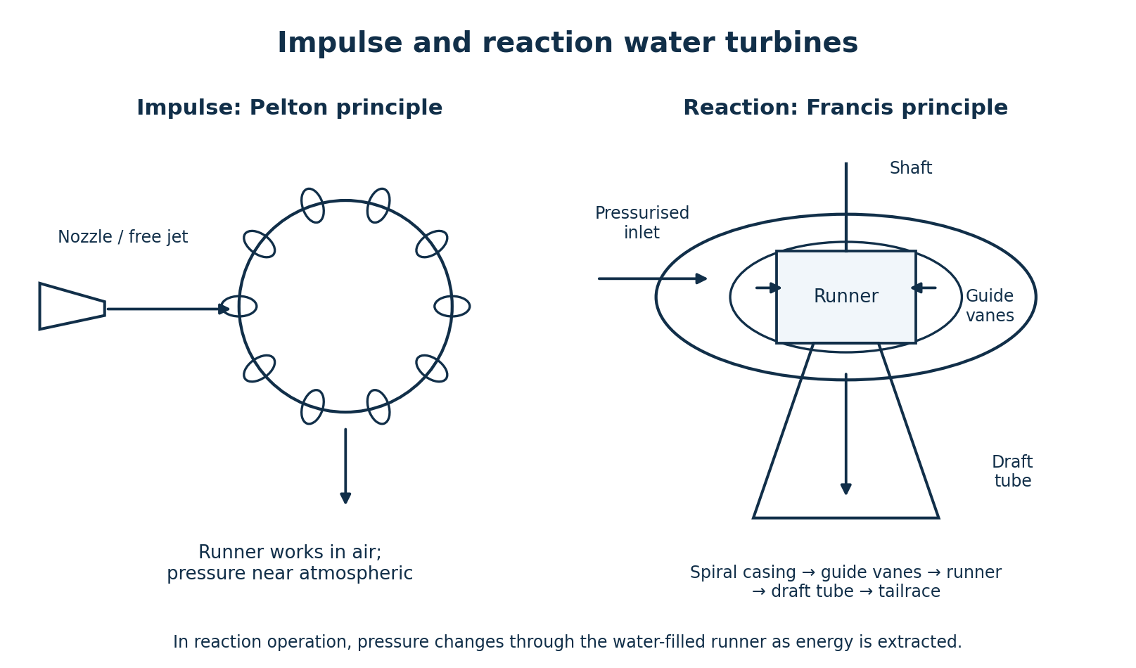
| Feature | Impulse | Reaction |
|---|---|---|
| Pressure-energy conversion | Main pressure drop occurs in the nozzle before the jet reaches the runner. | Pressure falls through the runner as well as associated stationary passages. |
| Runner flow | A free jet acts on buckets in an aerated space, approximately at atmospheric pressure. | The runner passages are filled with water under changing pressure. |
| Casing / outlet | Casing mainly contains splash; a draft tube is not required for the free-jet principle. | A pressure-containing casing and draft tube form part of the flow path. |
| Examples | Pelton; cross-flow impulse turbines. | Francis; Kaplan. |
Question 6(b)
With the aid of a diagram, explain the operation of a francis turbine used in a hydropower plant.
(5 marks)
Answer
- The penstock supplies pressurised water to the spiral casing around the runner.
- Stay/guide passages distribute flow; adjustable wicket gates regulate the quantity and direction of water entering the runner.
- Water moves inward through the runner and then turns toward the axial outlet. Changes in pressure and momentum produce runner torque.
- The shaft transmits power to the generator.
- The expanding draft tube carries discharge to the tailrace and recovers part of the remaining velocity head.
Question 6(c)
Explain the following methods used to store idle boilers (i) wet; (ii) dry.
(5 marks)
Answer
| Lay-up method | Explanation |
|---|---|
| Wet storage | Keep the boiler filled with suitably treated, deaerated water under the manufacturer’s preservation program, excluding oxygen and monitoring the specified chemistry. It is suited to appropriate short/standby periods where freezing is not a concern. |
| Dry storage | Drain, clean and thoroughly dry the boiler; exclude moisture using a controlled dry-air or desiccant arrangement. Inspect the preservation condition and remove preservation materials before recommissioning. |
Choice and detailed preservation conditions depend on boiler design, outage duration, ambient conditions and the approved maintenance program.
Question 6(d)
Outline the procedure of hydrostatic test of boilers.
(3 marks)
Answer
- Prepare the boiler under the authorised test plan: isolate it, make it safe for examination, fit the specified test connections/gauges, and fill with suitable water while venting trapped air.
- Use a controlled hydraulic source to raise pressure gradually to the test pressure specified by the applicable boiler procedure and authorised examiner; hold and inspect as required for leakage, deformation and pressure behaviour.
- Depressurise safely, drain/restore the required fittings, record findings and carry out the required checks before returning the boiler to service.
This is an examination outline. The paper gives no boiler rating or test standard, so no universal test pressure, hold time or temperature is invented. Compressed gas is not substituted for the hydrostatic test medium.
Question 7(a)
With the aid of sketches, explain the difference between vertical and horizontal wind turbines.
(6 marks)
Answer
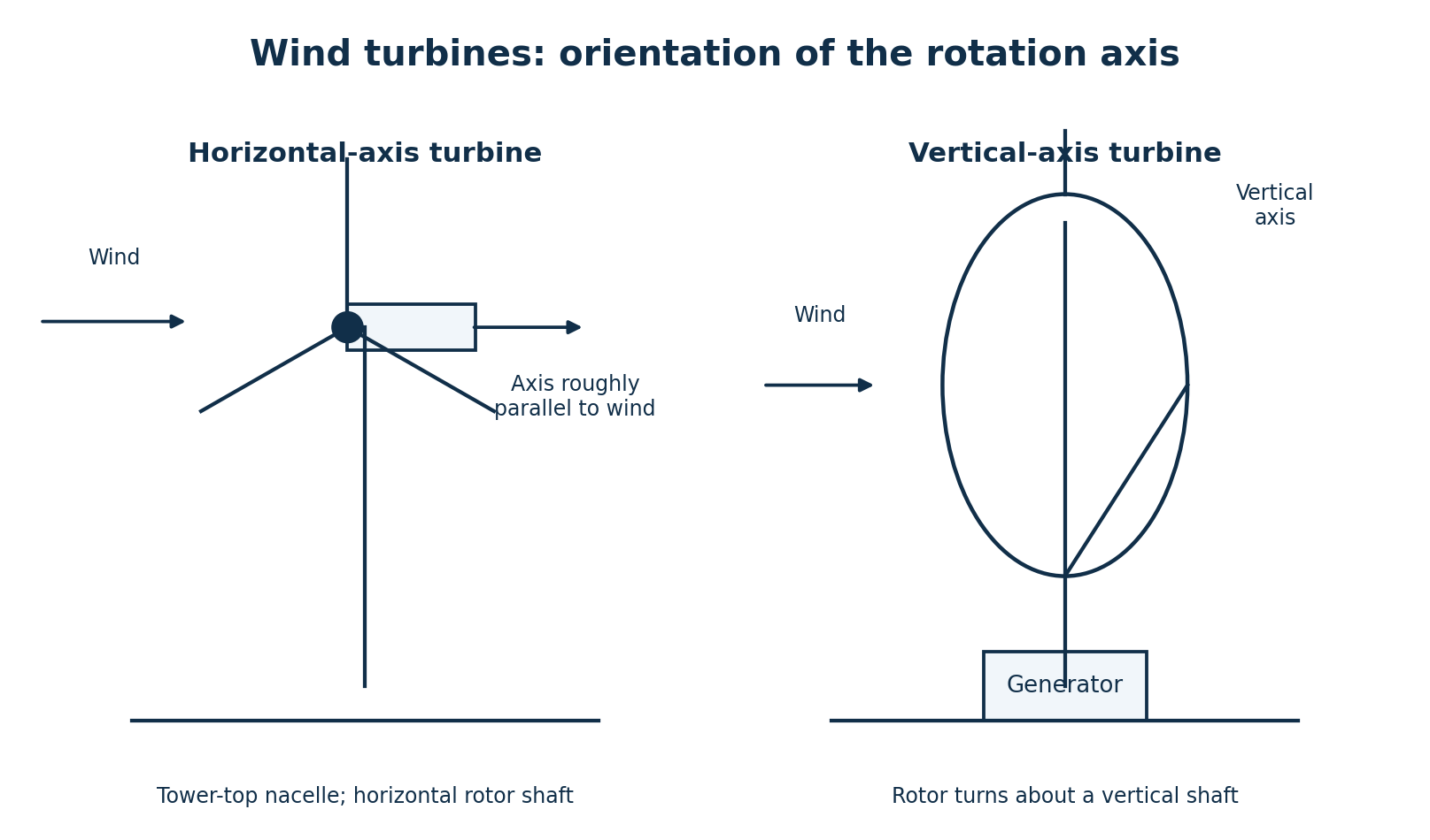
| Feature | Horizontal-axis wind turbine | Vertical-axis wind turbine |
|---|---|---|
| Axis | Rotor shaft is approximately horizontal, normally aligned with the wind. | Rotor rotates about a vertical shaft. |
| Rotor arrangement | Blades sweep a plane roughly perpendicular to the wind; a tower supports the nacelle. | Blades rotate around the upright shaft, for example Darrieus or Savonius arrangements. |
| Wind-direction response | Normally needs yaw alignment to face changing wind direction. | Can accept horizontal wind from different directions without yawing the rotor axis. |
| Drive placement | Generator/drive is commonly in the tower-top nacelle. | Some designs permit heavy drive components near ground level. |
The names describe the shaft orientation; a vertical-axis turbine does not require the wind itself to blow vertically.
Question 7(b)
With the aid of a sketches, explain the following methods of boiler feed water treatment: (i) internal; (ii) external.
(8 marks)
Answer
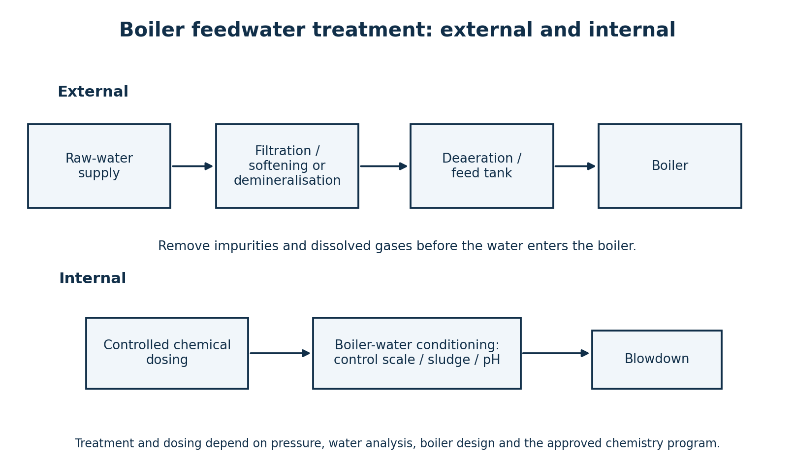
| Method | Where and how it acts | Examples / resulting control |
|---|---|---|
| Internal | Specified chemicals are dosed to condition residual impurities and maintain the required boiler-water chemistry. | Scale/sludge conditioning and pH/alkalinity control under an approved chemistry program; controlled blowdown removes concentrated dissolved/suspended material. |
| External | Impurities are removed or reduced before water enters the boiler. | Filtration removes solids; softening reduces hardness; demineralisation/RO reduces dissolved ions; deaeration reduces dissolved gases. |
Softening is not the same as complete demineralisation. Internal treatment supplements the required external treatment; it does not make arbitrarily poor feedwater acceptable. Treatment selection and dosing require the actual pressure, boiler type and water analysis.
Question 7(c)
(i) Outline three maintenance checks carried out on steam turbines. (ii) Outline two problems caused by wet steam in steam turbines.
(6 marks)
Answer
- Check lubrication condition, oil pressure/temperature and bearing condition.
- Trend vibration, alignment, seals and evidence of abnormal rubbing or leakage.
- Inspect/check the governing and protective systems, including scheduled overspeed-trip verification under the approved procedure.
- Wet-steam droplets can erode blades and associated flow surfaces, particularly at high relative velocity.
- Moisture increases flow losses and reduces stage efficiency; significant water carryover can also cause mechanical damage.