Control Systems and Instrumentation — March/April 2023
KNEC Diploma in Mechanical Engineering — Module III. Paper code: 2501/302; 2503/302; 2508/302; 2509/302. Time: 3 hours.
Questions are transcribed from the supplied examination paper. The independent revision answers are not official KNEC marking schemes. All 8 questions, including optional questions, are answered.
This paper consists of EIGHT questions in TWO sections; A and B. Answer FIVE questions by choosing at least TWO questions from each section. All questions carry equal marks. Maximum marks for each part of a question are as indicated. Questions 1–4 are Section A: Control Systems; Questions 5–8 are Section B: Instrumentation.
All eight questions, including optional questions, are answered. Original diagram signs, PLC instructions, numerical data and marks are retained. Question 7(b) is interpreted using tangential surface speed. The centimetre capacitor thicknesses are retained. The RTD coefficient is applied relative to 25°C as printed.
Question 1(a)
State the principle of superposition as used in control system.
(2 marks)
Answer
For a linear system, the response to a sum of inputs equals the sum of the responses to those inputs acting separately. Scaling an input by a constant scales its response by the same constant. For transfer-function calculations, compare responses with zero initial conditions, or account for the initial-condition response separately.
Question 1(b)
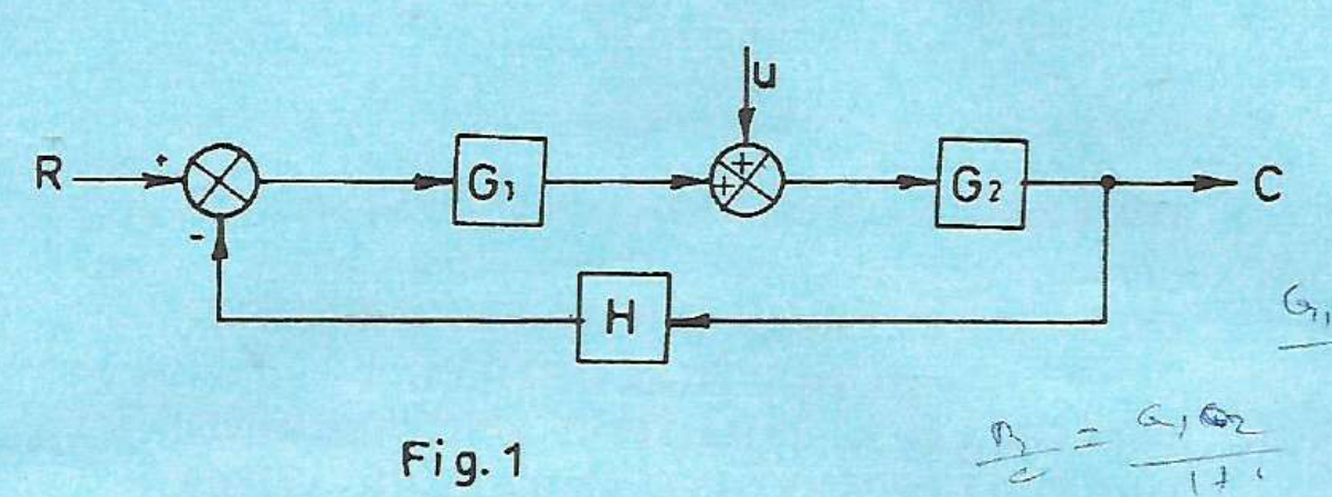
Figure 1 shows a block diagram of a control system. Determine the expression for the output C.
(9 marks)
Answer
Keep both inputs: R is the reference, and U is added positively at the summing point before G₂. The feedback to the first junction is negative.
| Step | Working |
|---|---|
| First summing point | E = R − HC. |
| Signal after G₁ | X = G₁E = G₁(R − HC). |
| Second summing point | Its output is X + U. |
| Pass through G₂ | C = G₂[G₁(R − HC) + U]. |
| Collect the terms in C | (1 + G₁G₂H)C = G₁G₂R + G₂U. |
| Solve for the output | C = [G₁G₂/(1 + G₁G₂H)]R + [G₂/(1 + G₁G₂H)]U. |
The first term is the response to R with U set to zero. The second is the response to U with R set to zero. Their sum applies superposition.
Question 1(c)
Explain each of the following with reference to control system: (i) error signal; (ii) control signal.
(4 marks)
Answer
| Term | Explanation |
|---|---|
| Error signal | The comparison signal between the reference and the measured feedback. For the negative-feedback arrangement, e(t) = r(t) − b(t). It indicates the discrepancy the controller is intended to reduce. |
| Control signal | The controller output supplied to the actuator or final control element. It changes the process input, for example a valve command or a motor-drive command, in response to the control law. |
Question 1(d)
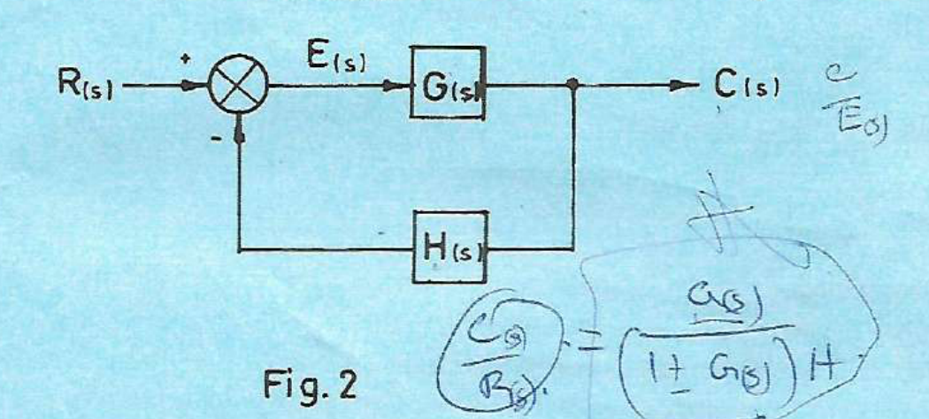
Figure 2 shows the basic canonical form of feedback control system. Determine the expression for the following: (i) C(s)/E(s); (ii) E(s)/R(s).
(5 marks)
Answer
| Step | Working |
|---|---|
| Forward block relation | C(s) = G(s)E(s). |
| Part (i) | C(s)/E(s) = G(s). |
| Negative-feedback relation | E(s) = R(s) − H(s)C(s). |
| Substitute C = GE | E(s) = R(s) − H(s)G(s)E(s). |
| Collect and divide | [1 + G(s)H(s)]E(s) = R(s), so E(s)/R(s) = 1/[1 + G(s)H(s)]. |
C/E is the forward-block gain. The closed-loop reference-to-output ratio, if also needed, is C/R = G/(1 + GH).
Question 2(a)
Define each of the following as used in signal flow graphs: (i) source node; (ii) sink node.
(2 marks)
Answer
| Node | Definition |
|---|---|
| Source node | An input node with outgoing branches and no incoming branches. |
| Sink node | An output node with incoming branches and no outgoing branches. |
Question 2(b)
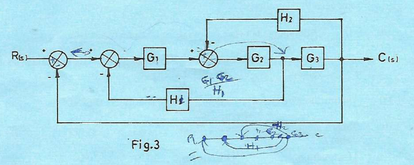
Figure 3 shows a block diagram of a control system. Draw a labelled equivalent signal flow graph.
(5 marks)
Answer
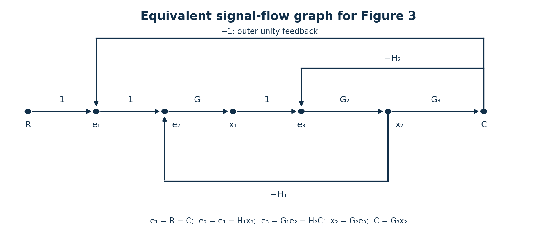
| Forward branch | Gain |
|---|---|
| R → e₁ | 1 |
| e₁ → e₂ | 1 |
| e₂ → x₁ | G₁ |
| x₁ → e₃ | 1 |
| e₃ → x₂ | G₂ |
| x₂ → C | G₃ |
| Feedback branch | Gain |
|---|---|
| C → e₁ | −1 |
| x₂ → e₂ | −H₁ |
| C → e₃ | −H₂ |
Each node equals the algebraic sum of its incoming branch signals. Thus e₁ = R − C, e₂ = e₁ − H₁x₂, x₁ = G₁e₂, e₃ = x₁ − H₂C, x₂ = G₂e₃ and C = G₃x₂. The reference R is a source node; C in this closed-loop graph has outgoing feedback branches and is therefore not a sink node.
Question 2(c)
(i) Describe mathematical models with reference to control system. (ii) Figure 4 shows a second order electrical system. Obtain its transfer function.
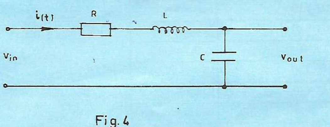
(8 marks)
Answer
(i) Mathematical models
A mathematical model expresses the relationships between a system’s inputs, internal variables and outputs using equations. It is derived from physical laws or identified from measurements and states its assumptions and parameters. Differential equations, transfer functions and state-space equations are common forms used to analyse dynamics and predict response.
(ii) RLC transfer function
The output is across the capacitor. Assume ideal R, L and C, no extra load and zero initial stored energy.
| Step | Working |
|---|---|
| Capacitor current | i(t) = C dV_out/dt. |
| Kirchhoff’s voltage law | V_in = Ri + L di/dt + V_out. |
| Substitute the capacitor current | V_in = RC dV_out/dt + LC d²V_out/dt² + V_out. |
| Laplace transform | V_in(s) = [LCs² + RCs + 1]V_out(s). |
| Form the ratio | V_out(s)/V_in(s) = 1/[LCs² + RCs + 1]. |
Question 2(d)
(i) Define servo system. (ii) Outline two distinguishing features of a.c and d.c servo systems.
(5 marks)
Answer
A servo system uses feedback to control a mechanical output, commonly position, velocity or torque, so that it follows a command.
| Feature | Classical a.c. servo | Classical d.c. servo |
|---|---|---|
| Motor excitation / drive | Uses an a.c.-excited servo motor and an appropriate a.c. drive. | Uses a d.c. servo motor and a controlled d.c. armature/field supply or equivalent d.c. drive. |
| How the command controls motion | Magnitude and phase/frequency relationships of the a.c. excitation determine the commanded torque, direction or speed for the chosen motor. | Armature current/voltage and its polarity are commonly used to control torque, speed and direction. |
These describe the usual textbook distinction. Modern electronically commutated servo drives require their particular motor/drive specification; brush construction alone does not define every present-day servo.
Question 3(a)
State three merits of analogue PID controllers.
(3 marks)
Answer
- They operate continuously, without the quantisation of a sampled digital signal.
- They can respond rapidly without waiting for a software sampling/computation cycle.
- A fixed-purpose loop can be implemented with a relatively simple analogue circuit without writing controller firmware.
Question 3(b)
Describe each of the following PID control modes: (i) Proportional mode; (ii) Integral mode; (iii) Derivative mode.
(6 marks)
Answer
| Mode | Control law and action |
|---|---|
| Proportional | u_P = K_Pe. The change in output is proportional to the present error. Increasing gain generally strengthens correction but excessive gain can reduce stability margin. |
| Integral | u_I = K_I∫e dt. The controller accumulates error over time and keeps changing its output while a sustained error exists. In a stable unsaturated loop it can remove steady offset for suitable inputs/disturbances. |
| Derivative | u_D = K_D de/dt. The output responds to the rate of change, providing anticipatory/damping action. Practical derivative action is filtered because differentiation amplifies high-frequency measurement noise. |
Question 3(c)
With the aid of a labelled schematic circuit diagram, describe the operation of an analogue PI controller.
(5 marks)
Answer
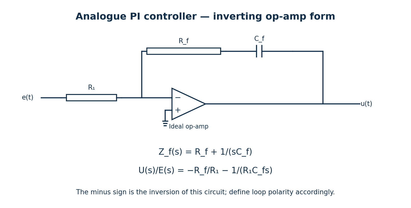
| Step | Working |
|---|---|
| Circuit configuration | Apply the error signal through R₁ to the inverting input. Ground the non-inverting input. Connect R_f and C_f in series from output to the inverting node. |
| Feedback impedance | Z_f(s) = R_f + 1/(sC_f). |
| Ideal op-amp gain | U/E = −Z_f/R₁ = −R_f/R₁ − 1/(R₁C_fs), assuming zero initial capacitor charge. |
| Proportional term | The resistive feedback produces magnitude K_P = R_f/R₁. |
| Integral term | The capacitor produces magnitude K_I = 1/(R₁C_f); accumulated error changes the output. |
| Polarity | This particular circuit inverts. Define the error/actuator sign or add an inverter so that the complete loop has the intended negative feedback. |
Question 3(d)
(i) Differentiate between hydraulic and pneumatic actuators. (ii) Draw a labelled schematic diagram of a 4-way pressure actuated spool valve.
(6 marks)
Answer
| Hydraulic actuator | Pneumatic actuator |
|---|---|
| Uses a pressurised liquid, usually oil. | Uses compressed gas, usually air. |
| The relatively incompressible working fluid gives a stiff drive and commonly supports high force density. | Gas compressibility makes the drive more compliant; air can be exhausted after use. |
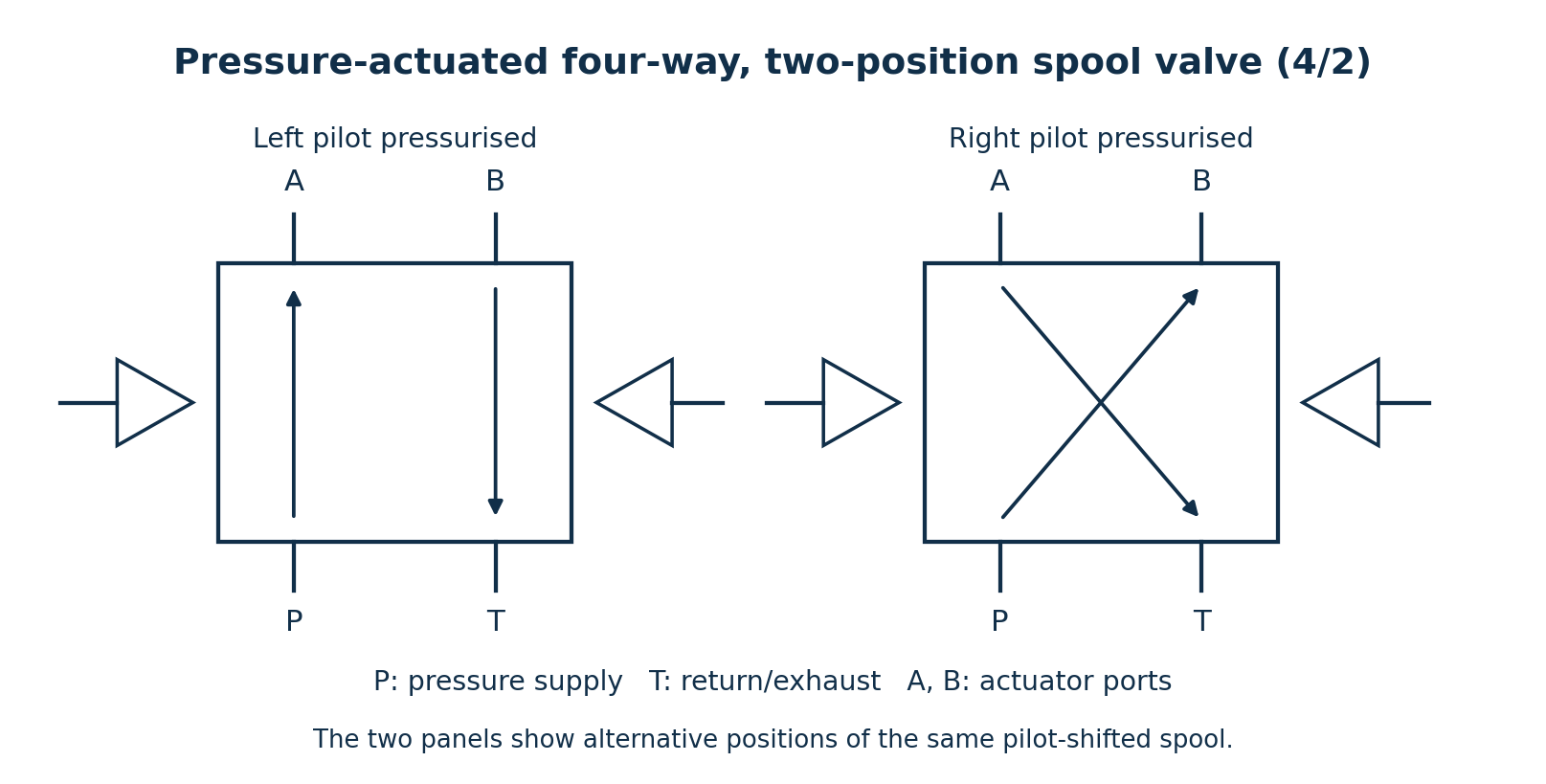
Pilot pressure acting on one spool end shifts the lands to connect P to A and B to T. Pressure at the opposite pilot shifts the spool to connect P to B and A to T. P is the supply, T the return/exhaust, and A/B lead to the actuator. The drawing shows a 4/2 example; a centre position was not specified in the question.
Question 4(a)
Outline three merits of programmable logic controllers (PLCs).
(3 marks)
Answer
- Control logic can be changed and expanded by modifying the program, reducing extensive relay rewiring.
- Industrial I/O and construction suit reliable operation in an appropriate industrial environment.
- Status monitoring and diagnostic functions make faults and sequence states easier to locate.
Question 4(b)
Table 1 shows a PLC instruction listing. (i) Draw the PLC ladder diagram. (ii) Describe the operation of the PLC control in b(i).
| Instruction | Comment |
|---|---|
| LD X10 | Push button 1 |
| OR Y10 | |
| ANI X11 | Push button 2 |
| OUT Y10 | Servo motor |
| OUT Y20 | Lamp 1 |
| LD X30 | Push button 3 |
| AND Y10 | |
| OUT Y30 | Lamp 2 |
| END | End of program |
(8 marks)
Answer
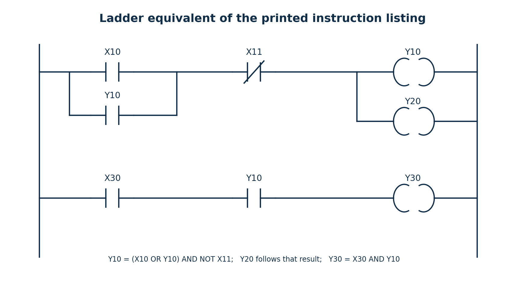
| Step | Working |
|---|---|
| First logic result | LD X10; OR Y10; ANI X11 produces (X10 OR Y10) AND NOT X11. |
| Servo and Lamp 1 | OUT Y10 stores this result in the servo-motor output. OUT Y20 stores the same accumulator result in Lamp 1. |
| Starting | With X11 = 0, setting X10 = 1 energises Y10 and Y20. |
| Holding | Y10’s parallel contact holds the first logic result true after X10 returns to 0, provided X11 stays 0. |
| Stopping | Setting X11 = 1 makes NOT X11 false, switching off Y10 and Y20 and breaking the seal-in path. |
| Lamp 2 | LD X30; AND Y10; OUT Y30 gives Y30 = X30 AND Y10. Lamp 2 is on only while X30 is true and the servo output is on. |
| End | END marks the end of the program, after which the PLC continues its normal scan cycle. |
The NC symbol for X11 is the program’s logical test of NOT X11. The paper does not specify physical push-button wiring; the explanation above states the actual bit values required by ANI.
Question 4(c)
Outline three economic benefits of process control to an industry.
(3 marks)
Answer
- More consistent product quality can reduce scrap, rework and rejected batches.
- Better regulation of material and energy use can reduce avoidable production costs.
- Repeatable automated operation can improve throughput and reduce labour spent on routine manual adjustments.
Question 4(d)
Explain each of the following process control strategies: (i) feedforward control; (ii) feedback control.
(6 marks)
Answer
| Strategy | Explanation and example |
|---|---|
| Feedforward | Measures a disturbance or another relevant input and changes the manipulated variable using a process relationship before the output error develops. For example, measured incoming material flow can set a corresponding heating command. Its success depends on the disturbance measurement and model. |
| Feedback | Measures the process output, compares it with the set-point and adjusts the manipulated variable according to the error. For example, measured outlet temperature determines a heating correction. It corrects the effects of disturbances that produce an observable error, including some that are not measured directly. |
The two strategies may be combined: feedforward supplies the expected correction and feedback trims the remaining error.
Question 5(a)
(i) Define the term pressure. (ii) State four factors governing pressure within a fluid.
(5 marks)
Answer
Pressure is the normal force per unit area: p = F_n/A, measured in pascals (N/m²).
For a static liquid of uniform density, p = p_surface + ρgh. Four factors are:
- The pressure applied at the liquid surface or reference level.
- The fluid density ρ.
- The depth h below that reference level.
- The gravitational acceleration g.
This is the hydrostatic interpretation. Flowing fluids can also have pressure changes associated with velocity and losses; those are not part of the static formula.
Question 5(b)
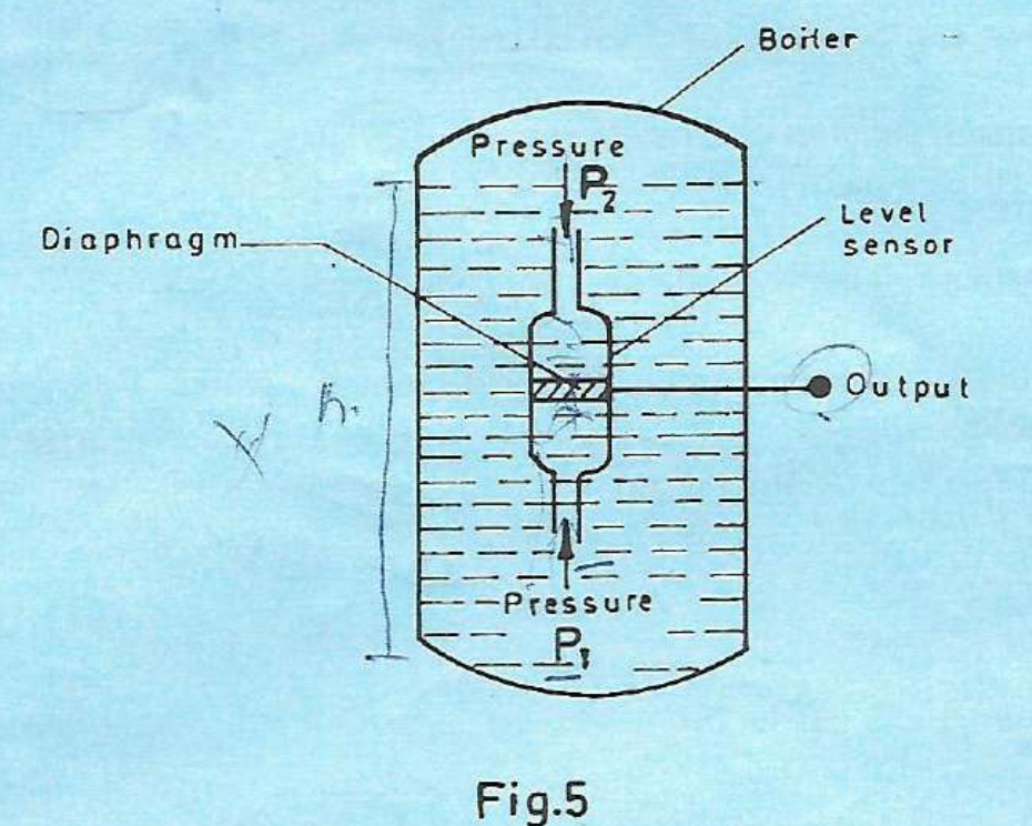
Figure 5 shows a boiler using liquid level sensor to ensure a certain minimum amount of liquid is maintained. (i) Identify the type of level sensor. (ii) Explain the operation of the sensor in b(i).
(6 marks)
Answer
The device is a differential-pressure (hydrostatic) level sensor using a diaphragm.
- The lower connection senses P₁, including the pressure from the liquid head. The upper connection senses the pressure P₂ above the liquid.
- The diaphragm is acted on by the pressure difference ΔP = P₁ − P₂, rather than by the boiler pressure alone.
- For a constant-density liquid and the indicated reference arrangement, ΔP = ρgh, after accounting for any fixed connection/reference-head offsets.
- A change in level changes the pressure difference and diaphragm displacement. A transducer converts that displacement to an electrical or other usable output.
- The calibrated output is compared with the minimum-level setting to command make-up water or the appropriate low-level action. Taking the pressure above the liquid as the reference compensates for changes in the common boiler pressure.
Question 5(c)
(i) Describe “pyroelectric detector”. (ii) Explain the effect of each of the following properties of pyroelectric materials: (I) pyroelectric coefficient; (II) dielectricity constant; (III) Specific heat capacity.
(9 marks)
Answer
A pyroelectric detector is a thermal radiation sensor whose absorbing element changes temperature when incident radiation changes. The temperature change alters the material’s spontaneous polarisation, producing charge/current that a high-impedance circuit converts into a signal. It responds to temperature changes; a steady unchanging temperature does not sustain the ideal pyroelectric current.
| Property | Effect |
|---|---|
| Pyroelectric coefficient p = dP_s/dT | It measures change of spontaneous polarisation per kelvin. For area A, ΔQ = pAΔT and i = pA dT/dt. A larger magnitude gives a larger charge/current for the same temperature change. |
| Dielectricity constant (relative permittivity ε_r) | For a plate element, C_e = ε₀ε_rA/d. For the same generated charge and geometry, V = Q/C_e, so greater permittivity reduces the ideal open-circuit voltage change. Real responsivity/noise also depends on the readout, frequency and dielectric loss. |
| Specific heat capacity c | With fixed mass, thermal capacity is mc. For a short absorbed-energy pulse with negligible heat loss, ΔT = E_abs/(mc). Smaller c produces a larger temperature change and signal; with fixed thermal conductance it also lowers the thermal time constant. |
Question 6(a)
(i) Define each of the following with reference to strain gauge: (I) stress; (II) strain. (ii) Explain the working principle of strain gauge.
(5 marks)
Answer
| Term | Definition |
|---|---|
| Stress | Internal force intensity. For uniform direct axial loading, σ = F/A in Pa. |
| Strain | Fractional change in dimension. For longitudinal strain, ε = ΔL/L; it is dimensionless. |
A bonded resistive strain gauge deforms with the surface to which it is attached. The resulting changes of length, cross-sectional area and resistivity change its electrical resistance. Within its calibrated elastic range, ΔR/R = GF·ε, where GF is the gauge factor. A bridge circuit converts the small resistance change to a measurable voltage; temperature effects require compensation.
Question 6(b)
With the aid of a labelled schematic circuit diagram, explain the operation of linear variable differential transformer (LVDT).
(8 marks)
Answer
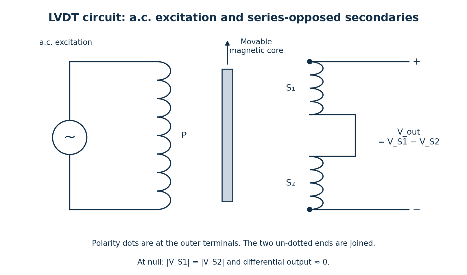
- The primary winding is supplied with a suitable a.c. excitation. A movable magnetic core links its flux to two secondary windings.
- The secondaries are connected in series opposition, so the measured output is the difference of their induced voltages, V_out = V_S1 − V_S2.
- At the central null position, coupling to the two secondaries is equal and the ideal differential output is zero.
- Moving the core toward S₁ increases its coupling relative to S₂; displacement toward S₂ produces the opposite imbalance.
- Within the calibrated linear range, output amplitude is proportional to displacement. The phase relative to the excitation changes by approximately 180° on reversing displacement about null.
- A phase-sensitive demodulator can convert this a.c. output into a signed d.c. displacement reading.
Question 6(c)
With the aid of a labelled block diagram, describe the elements of a digital instrumentation system.
(7 marks)
Answer
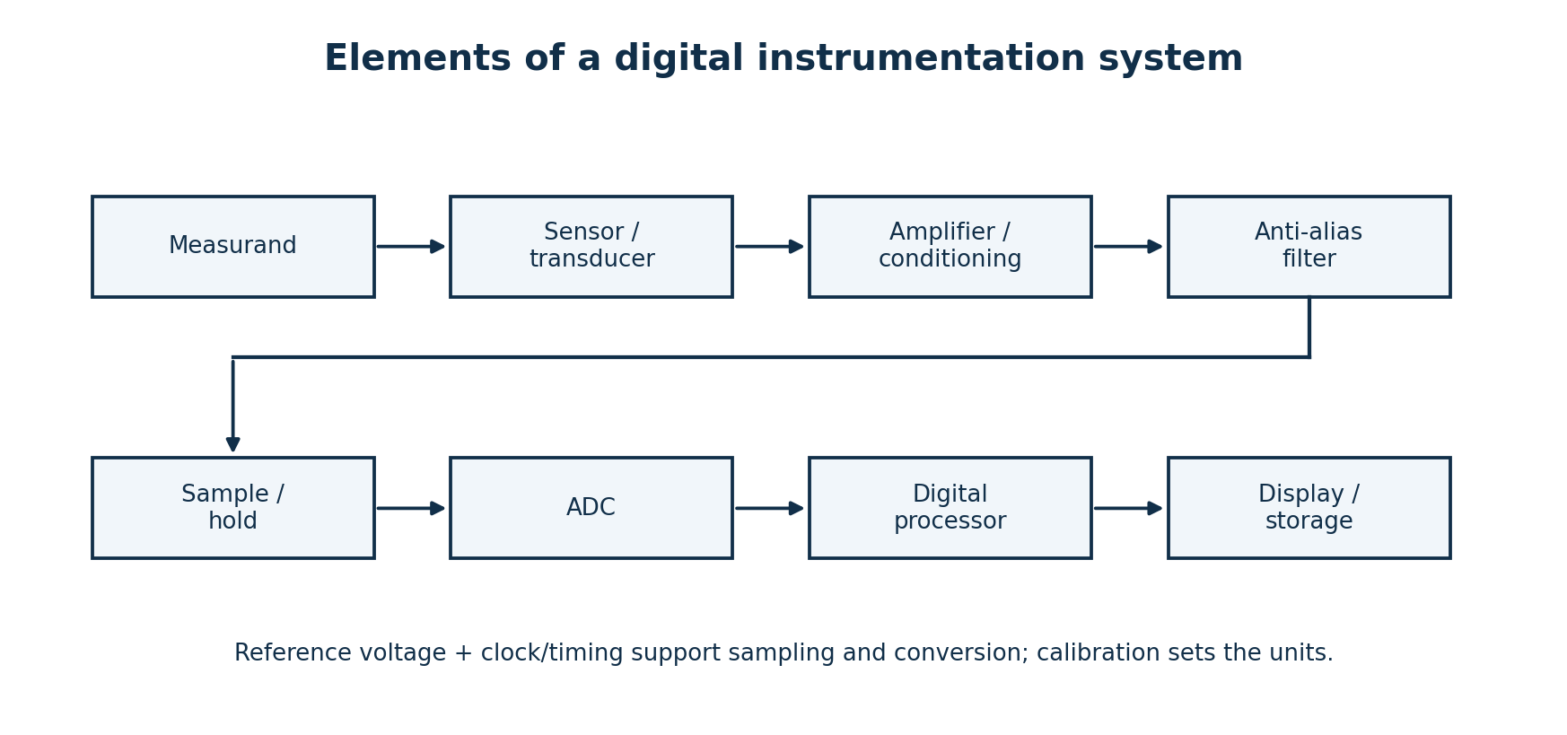
| Element | Function |
|---|---|
| Sensor/transducer | Converts the measurand into a suitable electrical signal. |
| Conditioning | Excites the sensor where necessary, amplifies/scales the signal, and may provide isolation or linearisation. |
| Anti-alias filter | Limits signal bandwidth before sampling to reduce aliasing. |
| Sample-and-hold | Captures a sufficiently stable input during conversion; often integrated into the ADC. |
| ADC | Quantises and encodes the analogue input as a digital number using a reference. |
| Digital processor | Applies calibration, scaling, computation and any digital filtering. |
| Display/storage/communication | Presents or records the result in the required engineering units. |
A clock/timing system and reference supply support sampling and conversion. Some physical instruments combine several of these blocks in one device.
Question 7(a)
(i) State two properties of piezo-electric crystals. (ii) Explain the piezoelectric effect.
(5 marks)
Answer
- Suitable crystals exhibit electromechanical coupling associated with a non-centrosymmetric crystal structure.
- They have high electrical insulation resistance, allowing generated surface charge to be sensed.
In the direct piezoelectric effect, an applied mechanical stress changes polarisation and creates charge on appropriate crystal faces. Over the operating range, generated charge is related to the applied force, commonly Q = dF for a suitable loading mode. A charge or voltage amplifier reads the output. The converse effect is deformation when an electric field is applied. Because real insulation and readout circuits leak charge, piezoelectric sensors are especially useful for dynamic force, pressure and vibration measurements.
Question 7(b)
(i) Distinguish between angular speed and torque. (ii) A shaft of diameter 6 cm rotates at a speed of 170 m/s. Determine the angular speed.
(5 marks)
Answer
| Quantity | Meaning |
|---|---|
| Angular speed | Rate of change of angular position, ω = dθ/dt, in rad/s. |
| Torque | Turning moment of a force about an axis, τ = F × perpendicular lever arm in magnitude, in N·m. |
The stated 170 m/s is a linear speed. Interpret it as the tangential speed at the surface of the 6 cm diameter shaft.
| Step | Working |
|---|---|
| Convert diameter | D = 6 cm = 0.06 m. |
| Find radius | r = D/2 = 0.03 m. |
| Use v = ωr | ω = v/r = 170/0.03. |
| Evaluate | ω = 5666.6667 rad/s. |
Question 7(c)
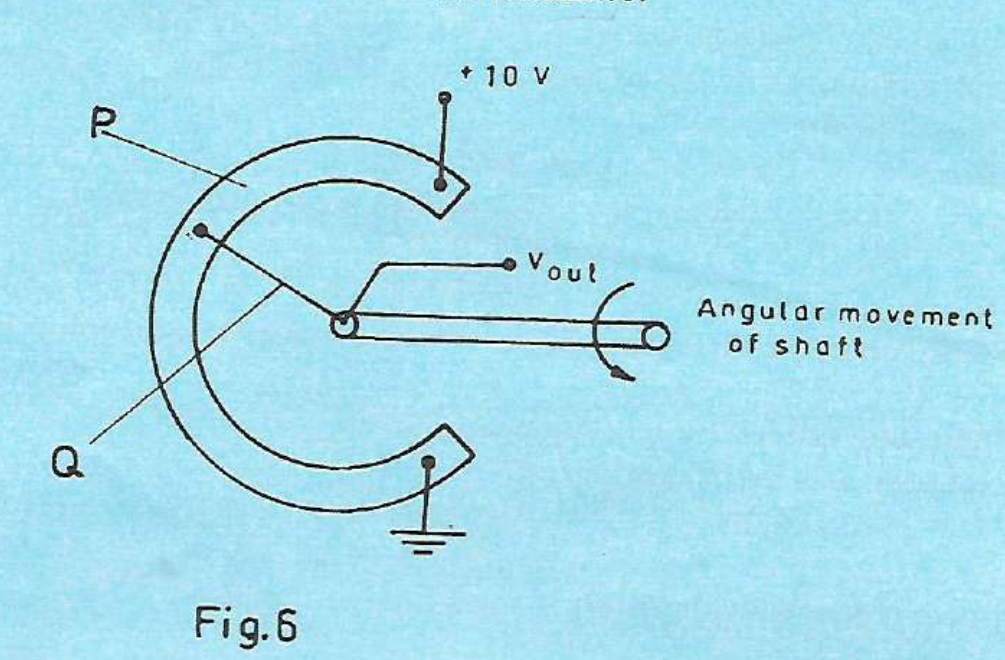
Figure 6 shows a mechanical shaft linked to a potentiometer. The shaft rotates through 330° from minimum to maximum resistance. (i) Identify the parts labelled P and Q. (ii) Determine the output voltage: (I) per degree turn; (II) for a turn of 170°.
(6 marks)
Answer
| Label | Part |
|---|---|
| P | Resistive track / resistance element. |
| Q | Moving wiper/contact connected to the rotating shaft. |
Assume a uniform linear potentiometer, negligible loading, and angle measured from the grounded minimum-output end shown.
| Step | Working |
|---|---|
| Supply and travel | The track has 10 V across 330°. |
| Sensitivity | k = 10/330 = 0.0303030 V/degree = 30.303 mV/degree. |
| Voltage at 170° | V_out = kθ = (10/330)(170) = 5.151515 V. |
Question 7(d)
Figure 7 shows a mica capacitive pressure sensor. The dielectric constant of mica is 6. When pressure is applied, the thickness of mica reduces to 2.1 cm. Determine the: (i) initial value of capacitance; (ii) change in capacitance. (Take the permittivity of free space as 8.84 × 10⁻¹² F/m).
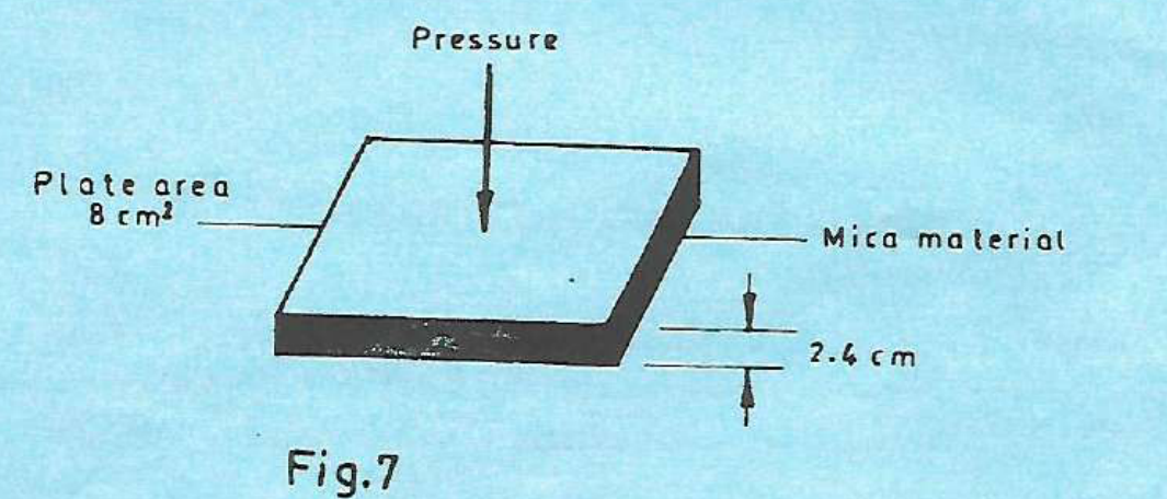
(4 marks)
Answer
Use the ideal parallel-plate formula C = ε₀ε_rA/d, treating the plate area and relative permittivity as constant. Retain the centimetre thicknesses printed in the figure and text.
| Step | Working |
|---|---|
| Convert the data | A = 8 cm² = 8 × 10⁻⁴ m²; d₁ = 2.4 cm = 0.024 m; d₂ = 2.1 cm = 0.021 m. |
| Initial capacitance | C₁ = (8.84 × 10⁻¹²)(6)(8 × 10⁻⁴)/0.024 = 1.768 × 10⁻¹² F. |
| Final capacitance | C₂ = (8.84 × 10⁻¹²)(6)(8 × 10⁻⁴)/0.021 = 2.020571 × 10⁻¹² F. |
| Change | ΔC = C₂ − C₁ = 0.252571 × 10⁻¹² F. The capacitance increases as the gap decreases. |
The printed spacing is large relative to the plate dimensions, so fringing would matter in a real device. These are the ideal parallel-plate results using the supplied values; the units have not been changed to millimetres.
Question 8(a)
(i) State three features of platinum resistance Temperature Detector (RTD). (ii) A platinum resistance thermometer has a resistance of 100 Ω at 25°C. The temperature co-efficient of resistance of platinum at 25°C is 0.00392/°C. Determine the: I. resistance of the platinum at 65°C II. temperature if the resistance of the platinum is 150 Ω.
(8 marks)
Answer
- Platinum has a positive temperature coefficient: its resistance increases with temperature.
- It provides stable and repeatable resistance-temperature behaviour when used within its specified range.
- Its response is approximately linear over limited ranges; more precise work uses a calibrated nonlinear relationship.
Use the linear approximation referenced to the supplied 25°C value, not to 0°C: R_T = R₂₅[1 + α₂₅(T − 25)].
| Step | Working |
|---|---|
| Resistance at 65°C | R₆₅ = 100[1 + 0.00392(65 − 25)] = 100(1.1568) = 115.68 Ω. |
| Rearrange for temperature | T = 25 + (R_T/R₂₅ − 1)/α₂₅. |
| Insert 150 Ω | T = 25 + (150/100 − 1)/0.00392 = 25 + 127.551020. |
| Result | T ≈ 152.55°C using the given linear model. |
Question 8(b)
Differentiate between each of the following with reference to measuring instruments: (i) indicating and recording instruments; (ii) analogue and digital instruments.
(4 marks)
Answer
| Pair | Difference |
|---|---|
| Indicating / recording | An indicating instrument displays the measured value at the time of observation. A recording instrument keeps a trace or stored record of values over time. One device can do both. |
| Analogue / digital | An analogue indication varies continuously, for example a pointer position. A digital indication represents the result as discrete numerical values/codes with finite resolution. |
Question 8(c)
Explain each of the following errors in measuring instruments: (i) environmental errors; (ii) observational errors.
(4 marks)
Answer
| Error | Explanation and example |
|---|---|
| Environmental | Error caused by external conditions affecting the instrument or measurement, such as temperature, humidity, vibration or electromagnetic interference. For example, ambient temperature can shift an uncompensated resistance reading. |
| Observational | Error introduced when observing or interpreting the indication, such as parallax, reading the wrong scale or incorrectly estimating a pointer position. Correct viewing and reading procedures reduce such errors. |
Question 8(d)
(i) Illustrate connection of resistive type humidity sensor to a potentiometric circuit. (ii) Write the expression for the signal output of the circuit in d(i).
(4 marks)
Answer
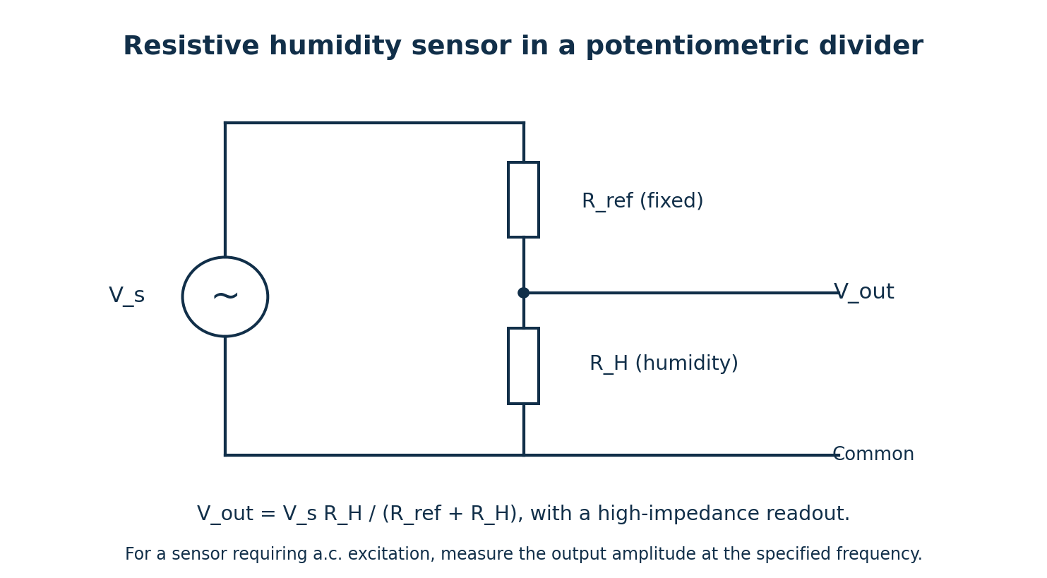
| Step | Working |
|---|---|
| Connect the divider | Connect R_ref and the humidity-sensitive resistance R_H in series across the excitation V_s. Read the junction voltage relative to the lower common terminal. |
| Assume negligible loading | Use a high-input-impedance readout, so the series current is I = V_s/(R_ref + R_H). |
| Output across the sensor | V_out = IR_H = V_sR_H/(R_ref + R_H). |
| Interpretation | Humidity changes R_H, causing a change in the output. A calibration relationship is needed to convert voltage to relative humidity. |
Many bare resistive humidity elements require a.c. excitation to avoid polarisation. Follow the element’s specified excitation; the diagram may be read in terms of a.c. amplitudes when resistance is a suitable approximation. If reactance matters, replace R_H by its complex impedance Z_H. If the output is taken across R_ref instead, the numerator changes to R_ref.