Fluid Mechanics and Thermodynamics — October/November 2023
KNEC Diploma in Mechanical Engineering — Module III. Paper code: 2501/304; 2502/304; 2503/304; 2508/304; 2509/304. Time: 3 hours.
Questions are transcribed from the supplied examination paper. The independent revision answers are not official KNEC marking schemes. All 7 questions, including optional questions, are answered.
Examination instruction: answer five questions in total, taking two from Section A (Questions 1–3) and three from Section B (Questions 4–7). All questions carry 20 marks.
Pressure values are treated as absolute in thermodynamic calculations. The printed 10 bar compressor intake and the pressure compression ratio in Q5(a) are retained. Friction-factor conventions and the missing steam temperature in Q7(b) are explained beside the answers.
Question 1(a)
Two reservoirs are connected by a pipe which has a diameter of 150 mm for the first 10 m and 225 mm for the remaining 12 m. The water surface in the upper reservoir is 10 m above the lower reservoir and the change of section is sudden. The coefficient of friction f is 0.01 for the smaller pipe and 0.015 for the larger pipe. Considering the energy losses at entry and exit, determine the rate of flow in m³/s.
(10 marks)
Answer
Use g = 9.81 m/s². Treat f as the pipe-friction coefficient in h_f = 4fLV²/(2gD), the convention commonly used with this form of question. Assume a sharp-edged entrance (Kentry = 0.5), a submerged reservoir exit (Kexit = 1), negligible free-surface velocities and no other fittings. The sudden enlargement also causes a loss.
| Step | Working |
|---|---|
| Continuity | A₁V₁ = A₂V₂; V₂ = (0.150/0.225)²V₁ = (4/9)V₁. |
| Available head | 10 = 0.5V₁²/(2g) + 4(0.01)(10/0.150)V₁²/(2g) + (V₁ − V₂)²/(2g) + 4(0.015)(12/0.225)V₂²/(2g) + V₂²/(2g). |
| Collect terms | 10 = [0.5 + 2.666667 + (5/9)² + (3.2 + 1)(4/9)²]V₁²/(2g) = 4.304938V₁²/(2g). |
| Pipe velocities | V₁ = √[2(9.81)(10)/4.304938] = 6.75097 m/s; V₂ = 3.00043 m/s. |
| Discharge | Q = (π/4)(0.150)²(6.75097) = 0.11930 m³/s. |
| Loss | Head (m) |
|---|---|
| Entrance | 1.1615 |
| Small-pipe friction | 6.1944 |
| Sudden enlargement | 0.7169 |
| Large-pipe friction | 1.4683 |
| Exit | 0.4588 |
Check: the five losses add to 10.000 m. If the supplied f values are instead defined as Darcy friction factors, omit the leading 4 in both friction terms: the corresponding result is Q = 0.18293 m³/s. State the factor convention rather than mixing the two.
Question 1(b)
The pressure drop ΔP in a viscous incompressible fluid flowing through a pipe of length L is dependent upon the fluid velocity V, the viscosity μ, internal diameter D of the pipe, density ρ of the fluid and the average variation of roughness in the pipe e. Using dimensional analysis, show that the pressure drop ΔP can be expressed as: ΔP = ρV² φ{Re, L/D, e/L}, where Re = Reynolds’ number; φ = function of.
(10 marks)
Answer
There are seven variables (ΔP, ρ, V, μ, D, L, e), involving three independent dimensions M, L and T. Buckingham’s theorem therefore gives four independent dimensionless groups. Choose ρ, V and D as repeating variables.
| Variable | Dimensions |
|---|---|
| ΔP | ML⁻¹T⁻² |
| ρ | ML⁻³ |
| V | LT⁻¹ |
| μ | ML⁻¹T⁻¹ |
| D, L, e | L |
| Step | Working |
|---|---|
| Pressure group | π₁ = ΔP ρᵃVᵇDᶜ. M: 1 + a = 0; T: −2 − b = 0; L: −1 − 3a + b + c = 0. Thus a = −1, b = −2, c = 0, giving π₁ = ΔP/(ρV²). |
| Viscosity group | π₂ = μρᵃVᵇDᶜ. Balancing M, T and L gives a = −1, b = −1, c = −1, hence π₂ = μ/(ρVD) = 1/Re. |
| Geometrical groups | π₃ = L/D and π₄ = e/D. |
| Functional relationship | ΔP/(ρV²) = F(1/Re, L/D, e/D). Since e/L = (e/D)/(L/D), e/L can replace e/D without losing information. |
| Required form | ΔP = ρV² φ(Re, L/D, e/L), where Re = ρVD/μ. Dimensional analysis determines the form, not the numerical function φ. |
Question 2(a)
Define the following terms as applied in fluid mechanics: (i) critical velocity; (ii) Reynold number.
(4 marks)
Answer
| Term | Definition |
|---|---|
| Critical velocity | The limiting mean flow velocity associated with transition between laminar and turbulent flow under specified conditions. For a circular pipe Vcrit = Recrit μ/(ρD). Transition depends on inlet disturbance and roughness; Re ≈ 2300 is a usual lower transition guide, not a universal sharp boundary. |
| Reynolds number | A dimensionless ratio of inertial to viscous effects: Re = ρV̄D/μ = V̄D/ν for pipe flow. Here V̄ is the cross-sectional mean velocity and ν = μ/ρ. |
Question 2(b)
(i) Show from first principles that the pressure loss due to laminar flow in a pipe is given by ΔP = 32ηLV̄/d², where η = viscosity of the fluid, L = length of the pipe, V̄ = mean velocity of flow and d = diameter of the pipe. (ii) A pipe of 110 mm diameter and 120 m long conveys oil of viscosity 0.45 kg/ms. If the pressure difference at the end of the pipe is 65 kN/m², determine the quantity of oil flowing through the pipe in m³/s.
(16 marks)
Answer
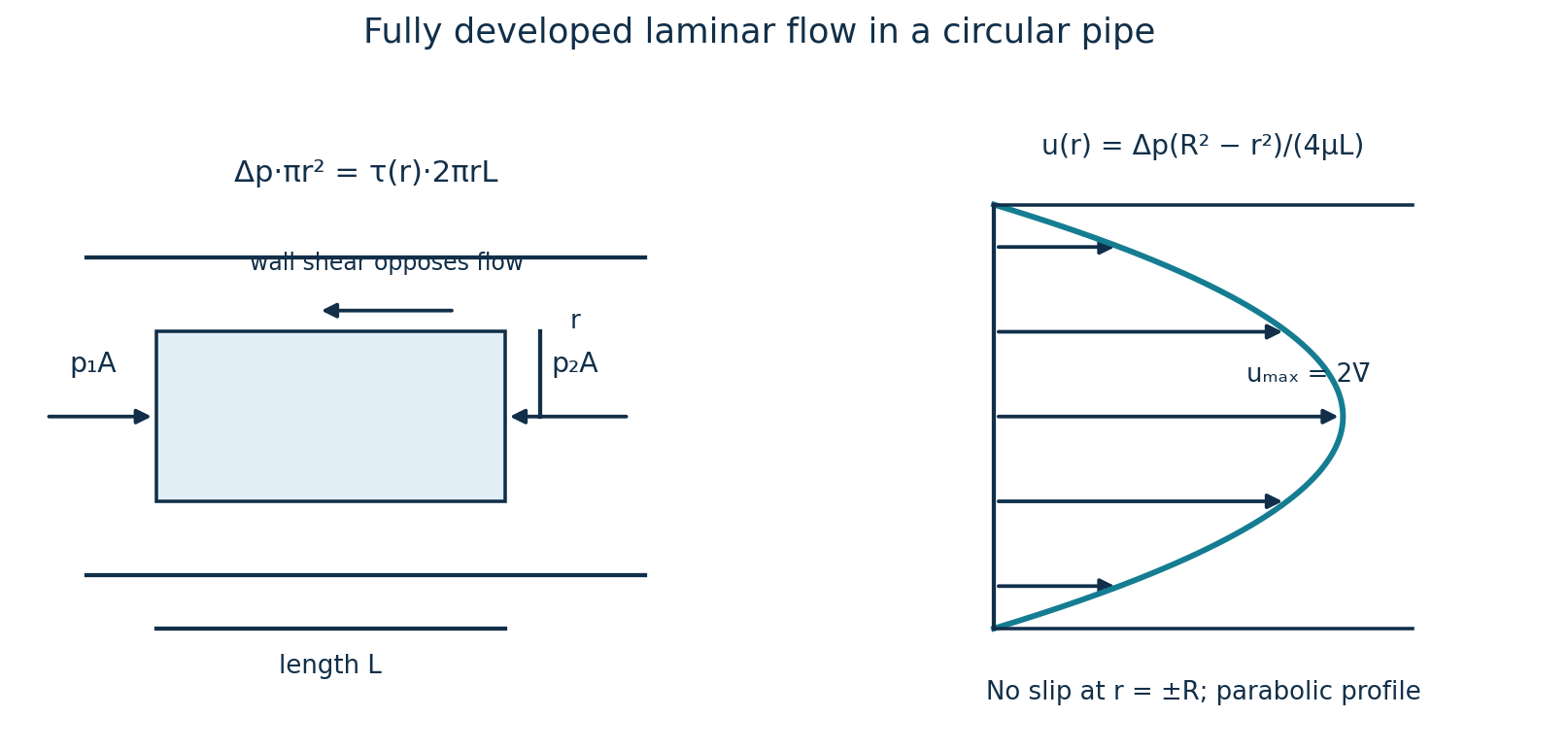
(i) Assume steady, fully developed, incompressible laminar flow of a Newtonian fluid in a straight horizontal circular pipe. Write its radius as R = d/2 and use η for dynamic viscosity.
| Step | Working |
|---|---|
| Axial force balance | For a coaxial fluid cylinder of radius r and length L: ΔP·πr² = τ(r)·2πrL, hence τ(r) = ΔP r/(2L). |
| Newton’s law of viscosity | Velocity decreases towards the wall: τ = −η du/dr. Thus du/dr = −ΔP r/(2ηL). |
| Integrate and apply no slip | u(r) = −ΔP r²/(4ηL) + C. At r = R, u = 0, so C = ΔP R²/(4ηL). Therefore u(r) = ΔP(R² − r²)/(4ηL). |
| Integrate the flow | Q = ∫₀ᴿ u(r)2πr dr = [πΔP/(2ηL)]∫₀ᴿ(R²r − r³)dr = πΔP R⁴/(8ηL). |
| Mean velocity | V̄ = Q/(πR²) = ΔP R²/(8ηL) = ΔP d²/(32ηL). Therefore ΔP = 32ηLV̄/d². |
(ii) Use the laminar relation derived above. No oil density is given, so a numerical Reynolds-number check cannot be completed; the result is conditional on laminar, fully developed flow.
| Step | Working |
|---|---|
| Convert data | d = 0.110 m; L = 120 m; η = 0.45 Pa·s; ΔP = 65,000 Pa. |
| Mean velocity | V̄ = ΔP d²/(32ηL) = 65,000(0.110)²/[32(0.45)(120)] = 0.455150 m/s. |
| Flow rate | Q = πd²V̄/4 = π(0.110)²(0.455150)/4 = 0.00432544 m³/s ≈ 4.325 L/s. |
Question 3(a)
(i) Define the term ‘cavitation’ as applied to pumps. (ii) With the aid of a sketch, explain the operation of a centrifugal pump.
(8 marks)
Answer
(i) Cavitation is the formation of vapour cavities when local liquid pressure falls below its vapour pressure, followed by their collapse on entering a higher-pressure region. Collapse can cause noise, vibration, surface pitting and loss of head or capacity.
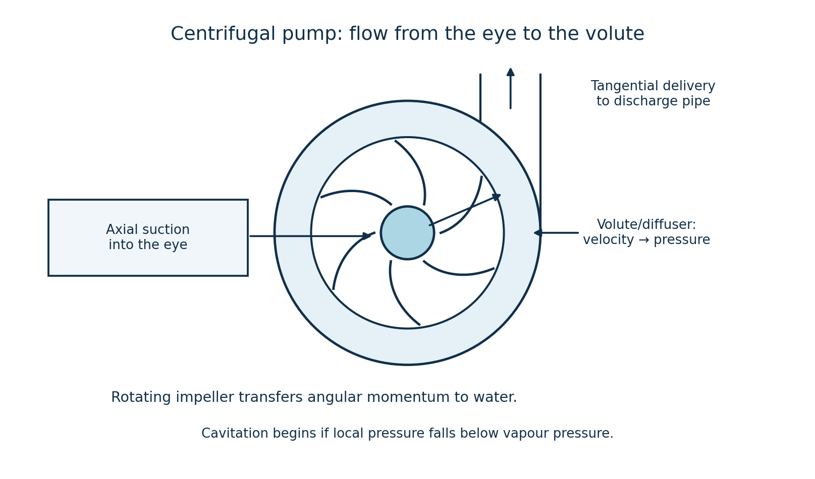
- (ii) Prime the casing and suction line so the impeller operates in liquid.
- The motor rotates the impeller. Liquid enters axially at the eye and is carried outward through the blade passages.
- The blades transfer angular momentum and mechanical energy to the liquid; the resulting lower pressure at the eye draws in more liquid from the supply.
- The volute or diffuser collects the high-velocity liquid and converts part of its velocity head into pressure head before discharge. Continuous flow follows while the pump is driven and its suction conditions are adequate.
Question 3(b)
The impeller of a centrifugal pump has external and internal diameters of 500 mm and 300 mm respectively. The width at the outlet is 60 mm and the pump runs at 1200 rev/min when working against a head of 48 m. The velocity of flow through the impeller is constant and equal to 3 m/s. The vanes are set back at an angle of 40° at the outlet. Calculate the: (i) inlet vane angle; (ii) work done by the impeller; (iii) manometric efficiency.
(12 marks)
Answer
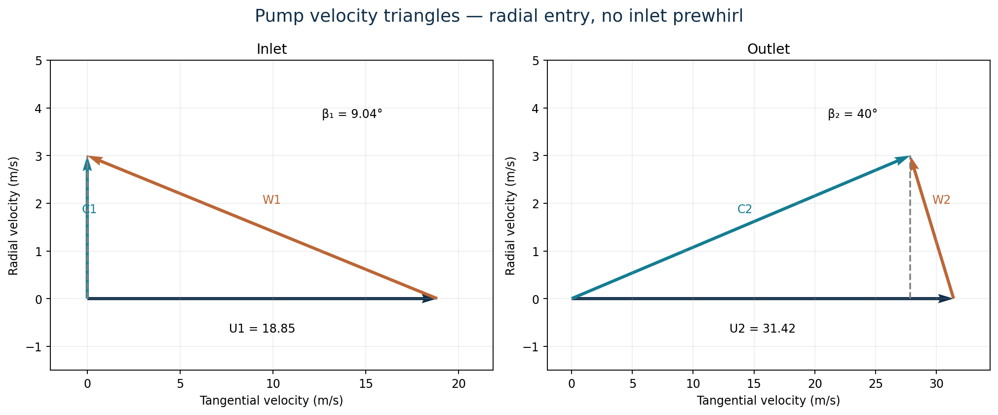
Assume radial entry without prewhirl (Vw₁ = 0), shockless entry, negligible blade-thickness blockage and no slip correction. Angles are measured from the local tangent. Use g = 9.81 m/s².
| Step | Working |
|---|---|
| Peripheral velocities | u₁ = πD₁N/60 = π(0.300)(1200)/60 = 18.8496 m/s; u₂ = π(0.500)(1200)/60 = 31.4159 m/s. |
| (i) Inlet blade angle | tan β₁ = Vf₁/u₁ = 3/18.8496; β₁ = 9.043°. |
| Outlet whirl velocity | Vw₂ = u₂ − Vf₂ cot β₂ = 31.4159 − 3 cot 40° = 27.8407 m/s. |
| (ii) Euler work per unit mass | w = u₂Vw₂ − u₁Vw₁ = 31.4159(27.8407) = 874.640 J/kg. Equivalent impeller head = w/g = 89.158 m. |
| Flow rate and rate of work | Q = πD₂b₂Vf₂ = π(0.500)(0.060)(3) = 0.282743 m³/s. For water at ρ ≈ 1000 kg/m³, impeller power transferred to the water = ρQw = 247.30 kW. This is fluid power at the impeller, not the unspecified shaft input. |
| (iii) Manometric efficiency | ηman = gHm/(u₂Vw₂) = 9.81(48)/874.640 = 0.53837 = 53.84%. |
Question 4(a)
State the first law of thermodynamics.
(2 marks)
Answer
Energy is conserved: it cannot be created or destroyed, but may be transferred as heat or work or converted between forms. For a closed system, ΔE = Q − W when heat into the system and work done by the system are positive. If kinetic and potential energy changes are negligible, ΔU = Q − W; over a complete cycle, ∮δQ = ∮δW.
Question 4(b)
A fluid at 0.75 bar occupying 0.09 m³ is compressed reversibly to a pressure of 3.5 bar according to the law pvⁿ = constant. The fluid is then heated reversibly at constant volume until the pressure is 4 bar; the specific volume is then 0.55 m³/kg. A reversible expansion according to a law pv² = constant restores the fluid to its initial state. Calculate the (i) mass of fluid present; (ii) value of the index n; (iii) net work done of the cycle.
(6 marks)
Answer
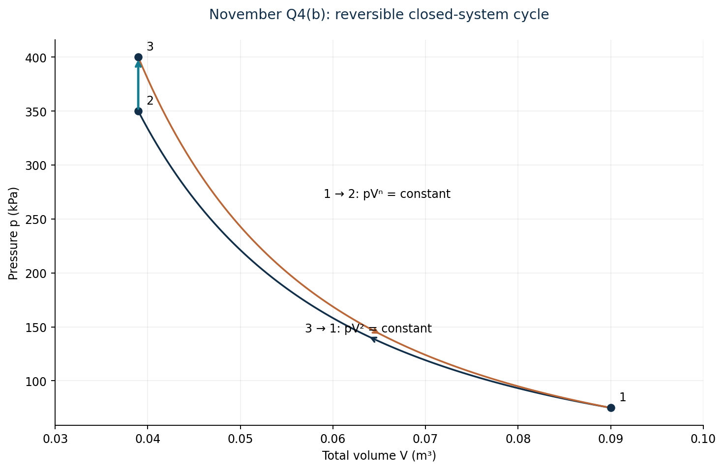
Label compression 1→2, constant-volume heating 2→3 and expansion 3→1. The fluid mass is fixed, so the same polytropic laws apply to total V and specific v. Use p in kPa so that pV is in kJ; take work done by the fluid as positive.
| Step | Working |
|---|---|
| Find V₃ from the return expansion | p₃V₃² = p₁V₁²; V₃ = V₁√(p₁/p₃) = 0.09√(0.75/4) = 0.0389711 m³. Since 2→3 is at constant volume, V₂ = V₃. |
| (i) Mass | m = V₃/v₃ = 0.0389711/0.55 = 0.0708566 kg. |
| (ii) Compression index | p₁V₁ⁿ = p₂V₂ⁿ; n = ln(3.5/0.75)/ln(0.09/0.0389711) = 1.840462. |
| Compression work | W₁₂ = (p₂V₂ − p₁V₁)/(1 − n) = [350(0.0389711) − 75(0.09)]/(1 − 1.840462) = −8.19775 kJ. |
| Heating and expansion work | W₂₃ = 0. W₃₁ = (p₁V₁ − p₃V₃)/(1 − 2) = [75(0.09) − 400(0.0389711)]/(−1) = 8.83846 kJ. |
| (iii) Net cycle work | Wnet = −8.19775 + 0 + 8.83846 = +0.640704 kJ per cycle, an output. |
Question 4(c)
Air at a pressure of 10 bar and temperature 20°C is compressed through a pressure ratio of 16/1 in a single acting, two stage reciprocating air compressor. Both stages have the same pressure ratio and the law of compression and expansion is PV¹·³ = constant. Intercooling is complete and the air mass flow rate is 3.5 kg/min. If the clearance volume of both stages is 6% of their respective swept volumes and the compressor runs at 250 rev/min, calculate the: (i) indicated power; (ii) swept volumes of the cylinders. Take Cp and R for air as 1.005 kJ/kgK and 0.287 kJ/kgK respectively.
(12 marks)
Answer
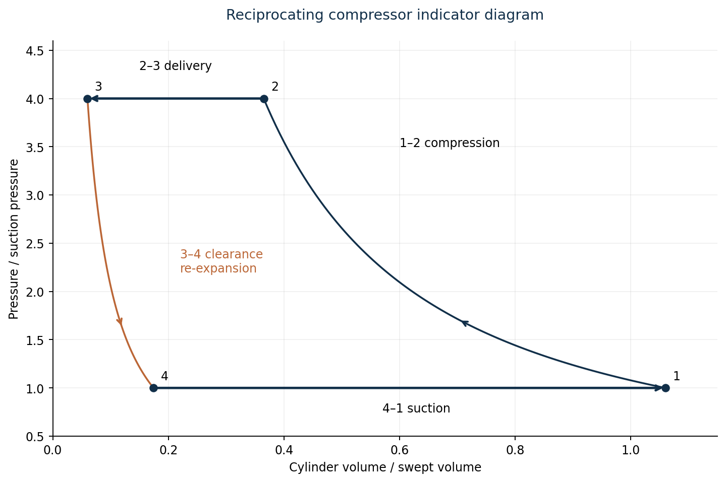
Use the printed 10 bar inlet pressure, treated as absolute. The total discharge pressure is therefore 160 bar. Perfect intercooling restores the high-pressure stage inlet to 293.15 K. Assume equal compression and clearance re-expansion indices, no valve pressure losses and one intake stroke per revolution in each cylinder.
| Step | Working |
|---|---|
| Stage pressures | rp,stage = √16 = 4. Intermediate pressure pi = 10×4 = 40 bar; delivery pressure = 40×4 = 160 bar. |
| Stage delivery temperature | Tdelivery = 293.15×4^[(1.3−1)/1.3] = 403.670 K before intercooling. |
| Specific indicated work | w = 2[n/(n−1)]RT₁[rp,stage^((n−1)/n) − 1] = 2(1.3/0.3)(0.287)(293.15)[4^(0.3/1.3) − 1] = 274.901 kJ/kg. |
| (i) Indicated power | ṁ = 3.5/60 = 0.0583333 kg/s. Pind = ṁw = 0.0583333(274.901) = 16.0359 kW. |
| Volumetric efficiency | ηv = 1 + C − C rp,stage^(1/n) = 1.06 − 0.06×4^(1/1.3) = 0.885709, the same in both stages. |
| Low-pressure suction volume rate | V̇LP = ṁRT₁/p₁ = 0.0583333(0.287)(293.15)/1000 = 0.00490782 m³/s. |
| (ii) LP swept volume per revolution | Vs,LP = V̇LP/[ηv(N/60)] = 0.00490782/[0.885709(250/60)] = 0.00132987 m³ = 1.32987 L. |
| HP swept volume per revolution | With equal inlet temperatures and pi = 4p₁, Vs,HP = Vs,LP/4 = 0.000332467 m³ = 0.332467 L. |
These are individual cylinder swept volumes, not volume rates. If a 1 bar intake were substituted, the swept volumes would be ten times as large while the specific work and power would be unchanged; that is not the pressure printed in this question.
Question 5(a)
0.5 kg of air is taken through a constant pressure cycle. The pressure and temperature of the air at the beginning of the adiabatic compression are 1 bar and 25°C respectively. The pressure ratio of compression is 10:1. Constant pressure heat addition occurs after the adiabatic compression until the volume is doubled. Determine the: (i) thermal efficiency; (ii) work ratio; (iii) mean effective pressure. Take γ = 1.4, R = 287 J/kgK and Cp = 1.005 kJ/kgK.
(10 marks)
Answer
Use the ideal Diesel cycle: 1→2 isentropic compression, 2→3 constant-pressure heating, 3→4 isentropic expansion to V₄ = V₁, and 4→1 constant-volume heat rejection. The stated 10:1 is a pressure ratio; the volume compression ratio must first be calculated. Use Cv = Cp − R = 1.005 − 0.287 = 0.718 kJ/(kg·K). The given constants have a small rounding inconsistency; retain γ = 1.4 for the isentropic relations.

| Step | Working |
|---|---|
| Compression and cutoff ratios | r = V₁/V₂ = (p₂/p₁)^(1/γ) = 10^(1/1.4) = 5.17947. Cutoff ratio ρc = V₃/V₂ = 2. |
| State temperatures | T₁ = 298.15 K; T₂ = T₁×10^[(γ−1)/γ] = 575.638 K; T₃ = 2T₂ = 1151.275 K; T₄ = T₃(2/r)^(γ−1) = 786.823 K. |
| Heat supplied | qin = Cp(T₃ − T₂) = 1.005(1151.275 − 575.638) = 578.516 kJ/kg. |
| Heat rejected | qout = Cv(T₄ − T₁) = 0.718(786.823 − 298.15) = 350.867 kJ/kg. |
| Net work | wnet = qin − qout = 227.649 kJ/kg. For 0.5 kg, Wnet = 113.824 kJ/cycle. |
| (i) Thermal efficiency | ηth = wnet/qin = 227.649/578.516 = 0.393505 = 39.35%. |
| Gross positive boundary work | w₂₃ = R(T₃−T₂) = 165.208 kJ/kg; w₃₄ = Cv(T₃−T₄) = 261.677 kJ/kg. Gross positive work = 426.885 kJ/kg. Compression input magnitude = Cv(T₂−T₁) = 199.236 kJ/kg. |
| (ii) Work ratio | Define work ratio as net work divided by all gross positive boundary work: 227.649/(165.208 + 261.677) = 0.53328 = 53.33%. |
| Displacement | v₁ = RT₁/p₁ = 0.287(298.15)/100 = 0.8556905 m³/kg; v₂ = v₁/r = 0.1652080 m³/kg. |
| (iii) Mean effective pressure | pm = wnet/(v₁ − v₂) = 227.649/(0.8556905 − 0.1652080) = 329.695 kPa = 3.29695 bar. |
Some texts define an alternative ratio using only the adiabatic expansion work in the denominator. With that explicitly different convention, wnet/w₃₄ = 0.86996. The gross-positive-work convention above includes the positive work during constant-pressure heating.
Question 5(b)
A gas turbine receives air at 15°C and compresses it 9.5 times the intake pressure using a compressor with an isentropic efficiency of 80%. The compressed air then passes through a heat exchanger, whose thermal ratio is 0.6. From the heat exchanger, the air passes through a combustion chamber and its temperature is raised to 1015°C. From the combustion chamber, the air expands through a turbine to the atmospheric pressure and is exhausted. The isentropic efficiency of the turbine is 0.82. The mass flow rate of the air is 2.5 kg/s. Taking the index of compression and expansion as 1.4, and Cp = 1.006 kJ/kgK, throughout, calculate the: (i) thermal efficiency; (ii) power output; (iii) work ratio; (iv) carnot efficiency within the cycle temperature limits.
(10 marks)
Answer
Assume no pressure losses, negligible fuel mass, equal air and exhaust mass flow, and no mechanical losses. Use 1 = compressor inlet, 2 = compressor outlet, r = regenerator cold outlet, 3 = turbine inlet and 4 = turbine outlet. Thermal ratio ε = (Tr−T₂)/(T₄−T₂). All temperature ratios use kelvin.

| Step | Working |
|---|---|
| Isentropic compressor outlet | a = (γ−1)/γ = 0.4/1.4. T₂s = 288.15×9.5^a = 548.237 K. |
| Actual compressor outlet | T₂ = T₁ + (T₂s−T₁)/ηc = 288.15 + (548.237−288.15)/0.80 = 613.259 K. |
| Turbine temperatures | T₃ = 1288.15 K. T₄s = T₃/9.5^a = 677.044 K. T₄ = T₃ − ηt(T₃−T₄s) = 787.043 K. |
| Recovered heat raises intake temperature | Since T₄ > T₂, regeneration is possible. Tr = T₂ + 0.6(T₄−T₂) = 717.529 K. |
| Specific work and heat | wt = Cp(T₃−T₄) = 504.114 kJ/kg; wc = Cp(T₂−T₁) = 327.059 kJ/kg; wnet = 177.054 kJ/kg. qin = Cp(T₃−Tr) = 574.044 kJ/kg. |
| (i) Thermal efficiency | ηth = wnet/qin = 177.054/574.044 = 30.843%. |
| (ii) Net power output | Pnet = ṁwnet = 2.5(177.054) = 442.636 kW. |
| (iii) Work ratio | wnet/wt = 177.054/504.114 = 0.351219 = 35.12%. |
| (iv) Carnot efficiency | ηCarnot = 1 − Tmin/Tmax = 1 − 288.15/1288.15 = 77.631%. This is a reversible temperature-limit benchmark. |
Question 6(a)
Steam at a pressure of 15 bar and a temperature of 225°C is expanded isentropically to a pressure of 3 bar. It is then further expanded hyperbolically to a pressure of 1.2 bar. Using the steam tables, determine the: (i) final condition of steam; (ii) change in entropy during the hyperbolic process. Take γ = 1.4.
(8 marks)
Answer
Use equilibrium water/steam properties. The values below are from IAPWS-IF97, rounded to steam-table precision; minor differences from printed tables are expected. Hyperbolic means pv = constant. A constant-γ ideal-gas approximation is not appropriate for these wet-steam states, so the supplied γ is not needed.
| Property | Value |
|---|---|
| At 15 bar, 225°C | s₁ = 6.59155 kJ/(kg·K). |
| Saturated properties at 3 bar | sf = 1.67176; sfg = 5.31980 kJ/(kg·K); vf = 0.00107318; vg = 0.605785 m³/kg. |
| Saturated properties at 1.2 bar | Tsat = 104.784°C; vf = 0.00104727; vg = 1.428445 m³/kg; sf = 1.36075; sfg = 5.93688 kJ/(kg·K). |
| Step | Working |
|---|---|
| First expansion: constant entropy | s₂ = s₁. At 3 bar, sf < s₂ < sg, so x₂ = (s₁−sf)/sfg = (6.59155−1.67176)/5.31980 = 0.924806. |
| Intermediate specific volume | v₂ = vf₂ + x₂(vg₂−vf₂) = 0.560315 m³/kg. |
| Hyperbolic expansion | p₂v₂ = p₃v₃; v₃ = (3/1.2)(0.560315) = 1.400787 m³/kg. |
| (i) Final condition | At 1.2 bar, vf < v₃ < vg. Hence the steam is wet, with x₃ = (v₃−vf)/(vg−vf) = (1.400787−0.00104727)/(1.428445−0.00104727) = 0.980623. Final temperature = 104.784°C; dryness = 98.062%. |
| Final entropy | s₃ = sf₃ + x₃sfg₃ = 1.36075 + 0.980623(5.93688) = 7.18260 kJ/(kg·K). |
| (ii) Specific entropy change | Δs₂₃ = s₃−s₂ = 7.18260−6.59155 = +0.591046 kJ/(kg·K). Total ΔS = mΔs if a mass is specified; no mass is supplied here. |
Question 6(b)
A single row impulse turbine has a mean blade speed of 220 m/s. The nozzles entry angle is 25° to the plane of rotation of the blades. The steam velocity from the nozzle is 600 m/s. There is 15% loss of relative velocity due to friction losses across the blades. The absolute velocity at exit is in the axial direction. The steam flows through the turbine at a rate of 700 kg/hr. Determine the: (i) inlet and exit blade angles; (ii) absolute velocity of the steam at exit; (iii) power output of the turbine.
(12 marks)
Answer
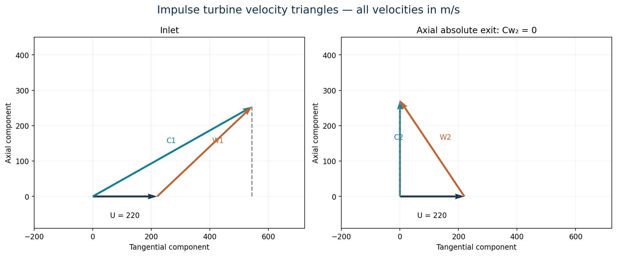
Let C denote absolute velocity, W relative velocity, U blade speed, Cw tangential whirl and Ca axial velocity. Blade angles β are measured from the tangent, with the exit relative velocity directed backward. The relation is C = U + W. Assume shockless entry and use diagram power without unspecified mechanical losses.
| Step | Working |
|---|---|
| Resolve nozzle velocity | Cw₁ = 600 cos 25° = 543.785 m/s; Ca₁ = 600 sin 25° = 253.571 m/s. |
| Inlet relative triangle | Wt₁ = Cw₁−U = 323.785 m/s; W₁ = √(323.785²+253.571²) = 411.260 m/s. |
| (i) Inlet blade angle | β₁ = tan⁻¹[Ca₁/(Cw₁−U)] = tan⁻¹(253.571/323.785) = 38.066°. |
| Exit relative speed | W₂ = 0.85W₁ = 349.571 m/s. Axial absolute discharge means Cw₂ = 0, so Wt₂ = −U = −220 m/s. |
| (i) Exit blade angle | W₂ cos β₂ = U; β₂ = cos⁻¹(220/349.571) = 50.998°. |
| (ii) Absolute exit speed | C₂ = Ca₂ = √(W₂²−U²) = √(349.571²−220²) = 271.661 m/s. |
| (iii) Power output | ṁ = 700/3600 = 0.194444 kg/s. P = ṁU(Cw₁−Cw₂) = 0.194444(220)(543.785−0) = 23,261.9 W = 23.262 kW. |
Question 7(a)
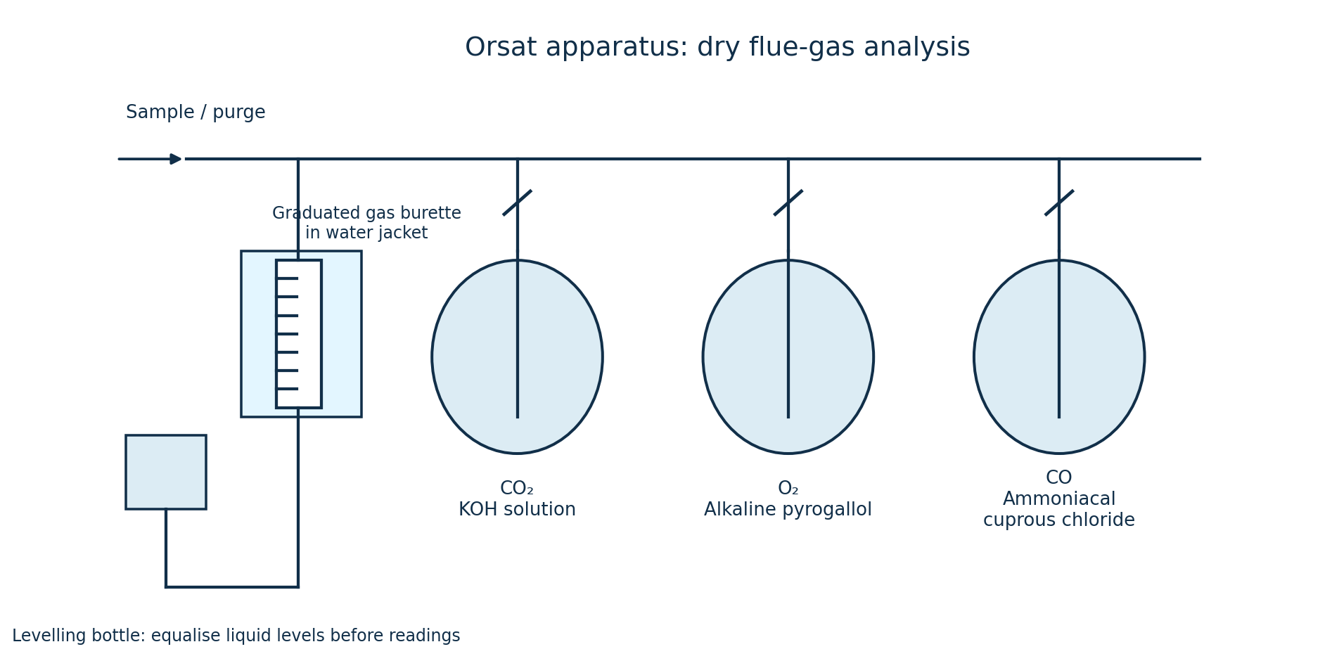
Sketch the Orsat apparatus and indicate the absorbent used to measure the content of the gases in the exhaust.
(8 marks)
Answer
| Order | Gas measured | Absorbent |
|---|---|---|
| 1 | Carbon dioxide, CO₂ | Potassium hydroxide (caustic potash) solution. |
| 2 | Oxygen, O₂ | Alkaline pyrogallol solution. |
| 3 | Carbon monoxide, CO | Ammoniacal cuprous chloride solution. |
- Take a measured dry flue-gas sample, usually 100 mL, into the graduated burette. The water jacket helps keep its temperature stable.
- Equalise the liquid levels in the burette and levelling bottle so each volume reading is made at the same pressure.
- Pass the sample into the CO₂ pipette and back until the volume no longer changes. Repeat for O₂, then CO. Each volume reduction is the volume of that absorbed gas.
- For an initial 100 mL sample, a reduction of x mL represents x% by volume on a dry basis. Nitrogen and other unabsorbed gases remain; calling the remainder nitrogen assumes other residual gases are negligible.
Question 7(b)
A steam pipe which has 150 mm external diameter, carries steam at a pressure of 40 bar. It is covered with two layers of lagging each 40 mm thick. The coefficients of thermal conductivity for the two layers are 0.08 W/mK for the inner layer and 0.05 W/mK for the outer layer. The surface transfer coefficient for the outer surface is 7.0 W/m²K. The length of the pipe is 50 m and the ambient temperature is 25°C. Calculate the: (i) heat loss; (ii) interface temperatures.
(12 marks)
Answer
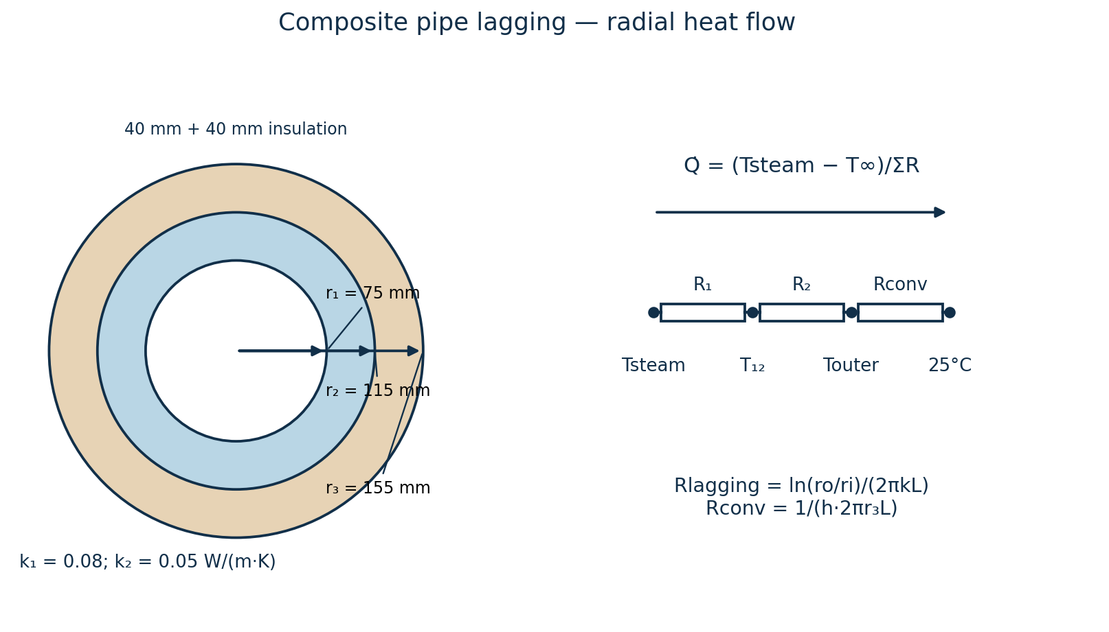
The pressure alone does not determine the temperature of superheated steam. For a numerical answer, assume saturated steam at 40 bar absolute: Ts = 250.358°C. Also neglect steam-side film resistance and pipe-wall resistance, so the pipe outer surface is at Ts. Assume steady radial conduction with constant k, negligible end losses and the given external heat-transfer coefficient.
| Step | Working |
|---|---|
| Radii | r₁ = 0.150/2 = 0.075 m; r₂ = 0.075+0.040 = 0.115 m; r₃ = 0.115+0.040 = 0.155 m. L = 50 m. |
| Inner lagging resistance | R₁ = ln(r₂/r₁)/(2πk₁L) = ln(0.115/0.075)/[2π(0.08)(50)] = 0.01700746 K/W. |
| Outer lagging resistance | R₂ = ln(r₃/r₂)/(2πk₂L) = ln(0.155/0.115)/[2π(0.05)(50)] = 0.01900265 K/W. |
| External surface resistance | Rconv = 1/(h·2πr₃L) = 1/[7(2π)(0.155)(50)] = 0.00293373 K/W. |
| (i) Heat loss | ΣR = 0.03894384 K/W; Q̇ = (250.358−25)/ΣR = 5786.73 W = 5.78673 kW for 50 m, or 115.735 W/m. |
| (ii) Between the two laggings | T₁₂ = Ts − Q̇R₁ = 250.358−5786.73(0.01700746) = 151.940°C. |
| Outer lagging surface | To = T∞ + Q̇Rconv = 25+5786.73(0.00293373) = 41.977°C. The pipe/inner-lagging boundary is at the assumed 250.358°C. |
| Check | T₁₂−To = Q̇R₂ ≈ 109.963°C, matching the outer-layer temperature drop. |
If the actual steam temperature is another value Tsteam, retain Q̇ = (Tsteam−25)/0.03894384 W, T₁₂ = Tsteam−0.01700746Q̇ and To = 25+0.00293373Q̇. An unconditional numerical answer is not possible without the temperature or the saturation assumption.