Fluid Mechanics and Thermodynamics — March/April 2023
KNEC Diploma in Mechanical Engineering — Module III. Paper code: 2501/304; 2502/304; 2503/304; 2508/304; 2509/304. Time: 3 hours.
Questions are transcribed from the supplied examination paper. The independent revision answers are not official KNEC marking schemes. All 7 questions, including optional questions, are answered.
Examination instruction: answer five questions in total, taking two from Section A (Questions 1–3) and three from Section B (Questions 4–7). All questions carry 20 marks.
The source uses ρ for pressure loss in Q1(a), has an incorrect gas-constant symbol in Q6(a), omits the compressor index in Q6(b), and does not state a turbine efficiency in Q7(b). These are identified without silently changing the questions; conditional calculations are clearly labelled.
Question 1(a)
Working from first principles, show that the loss of pressure due to laminar flow in a horizontal circular pipe is given by: ρ = 32μVL/d². Where: μ = coefficient of viscosity of the fluid, V = mean velocity of flow, L = length of pipe, d = diameter of the pipe.
(12 marks)
Answer
The printed equation uses ρ for pressure loss. In this answer write that pressure loss as Δp to avoid confusing it with mass density. Assume steady, incompressible, fully developed laminar flow of a Newtonian fluid in a straight horizontal pipe with no slip at its wall.
| Step | Working |
|---|---|
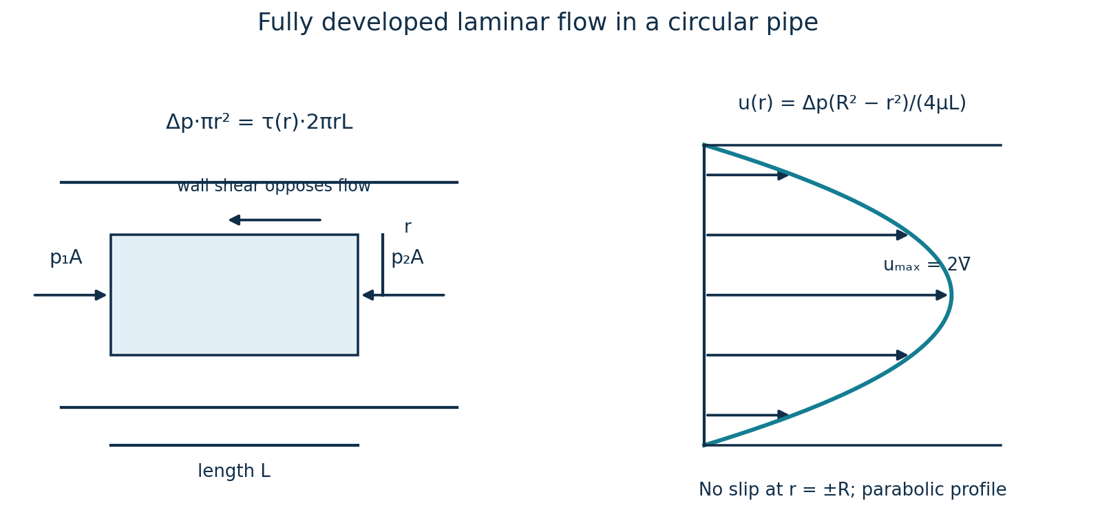
| Force balance | Take a coaxial fluid cylinder of radius r and length L inside the pipe. Its net pressure force is Δp·πr² and its resisting shear force is τ(r)·2πrL. Thus τ(r) = Δp r/(2L). |
| Viscous stress | With axial velocity u decreasing towards the wall, τ = −μ du/dr. Therefore du/dr = −Δp r/(2μL). |
| Velocity profile | Integrating gives u = −Δp r²/(4μL) + C. No slip at r = R = d/2 gives C = ΔpR²/(4μL). Hence u(r) = Δp(R²−r²)/(4μL). |
| Volume flow | Q = ∫₀ᴿu(r)2πr dr = [πΔp/(2μL)]∫₀ᴿ(R²r−r³)dr = πΔpR⁴/(8μL). |
| Mean velocity | V = Q/(πR²) = ΔpR²/(8μL) = Δpd²/(32μL). |
| Required result | Δp = 32μVL/d². The units are (Pa·s)(m/s)(m)/m² = Pa. Also umax = ΔpR²/(4μL) = 2V. |
Question 1(b)
Oil of viscosity 1.44 kg/ms and specific gravity 0.9 flows through a pipeline of length 500 m long and diameter 90 mm at a pressure of 1800 kN/m². Calculate the: (i) velocity along the centre of the pipe; (ii) maximum shear stress; (iii) power required to maintain the flow; (iv) velocity at 20 mm from the pipe wall.
(8 marks)
Answer
Interpret the stated 1800 kN/m² as the pressure drop across this horizontal pipe, for example an inlet gauge pressure with discharge at atmospheric pressure. If it is only an absolute pressure at one point, the pressure difference is missing. Use μ = 1.44 Pa·s and density ρ = 0.9×1000 = 900 kg/m³.
| Step | Working |
|---|---|
| Mean velocity and flow regime | V = Δpd²/(32μL) = 1.8×10⁶(0.090)²/[32(1.44)(500)] = 0.6328125 m/s. Re = ρVd/μ = 900(0.6328125)(0.090)/1.44 = 35.60, confirming laminar flow. |
| (i) Centreline velocity | umax = 2V = 1.265625 m/s. |
| (ii) Maximum shear stress | τ(r) = Δp r/(2L), largest at the wall r = d/2. τw = Δpd/(4L) = 1.8×10⁶(0.090)/[4(500)] = 81.0 Pa. |
| Flow rate | Q = πd²V/4 = π(0.090)²(0.6328125)/4 = 0.00402578 m³/s. |
| (iii) Hydraulic power | P = ΔpQ = 1.8×10⁶(0.00402578) = 7246.40 W = 7.2464 kW. A pump shaft would require P/ηpump if its efficiency were specified. |
| (iv) Position measured from the wall | R = 45 mm. A point 20 mm from the wall has r = 45−20 = 25 mm = 0.025 m from the centre. |
| Velocity at that point | u = umax[1−(r/R)²] = 1.265625[1−(25/45)²] = 0.8750 m/s. |
Question 2(a)
Define the following terms as applied to centrifugal pumps: (i) overall efficiency; (ii) manometric efficiency; (iii) mechanical efficiency.
(3 marks)
Answer
| Efficiency | Definition |
|---|---|
| Overall | ηo = useful hydraulic output / shaft input = ρgQHm/Pshaft. |
| Manometric | ηman = manometric head / Euler head = gHm/(u₂Vw₂−u₁Vw₁). It compares the actual total head gained by the delivered liquid with ideal impeller energy transfer. |
| Mechanical | ηmech = power transferred by the impeller to the liquid / shaft power supplied. The difference accounts for mechanical losses such as bearing, seal and disk-friction losses, under the convention used. |
Question 2(b)
State three effects that cause energy losses in centrifugal pumps.
(3 marks)
Answer
- Hydraulic friction, turbulence, separation and shock at blade entry or through the impeller/volute dissipate fluid energy.
- Leakage or internal recirculation through clearances diverts flow from useful delivery and wastes transferred energy.
- Mechanical friction in bearings and seals, and impeller disk friction, absorbs shaft power.
Question 2(c)
A centrifugal pump having internal and external impeller diameter of 160 mm and 255 mm respectively delivers 0.055 m³ of water per second when running at a speed of 1560 rpm. The velocity of flow through the impeller is constant at 3 m/s. The blades are curved backwards at an angle of 30° to the tangent at the exit. The diameter of the suction and delivery pipes are 150 mm and 100 mm respectively. The pressure head at suction is 4 m below and that of delivery is 18 m above the atmospheric pressure. If the power required to drive the pump is 22 kW. Determine the: (i) inlet vane angle; (ii) overall pump efficiency; (iii) manometric efficiency.
(14 marks)
Answer
Assume water density 1000 kg/m³, g = 9.81 m/s², radial impeller entry without prewhirl, negligible slip/blockage, and suction and delivery pressure tappings at the same elevation. Include the difference in pipe velocity heads when calculating manometric head.
| Step | Working |
|---|---|
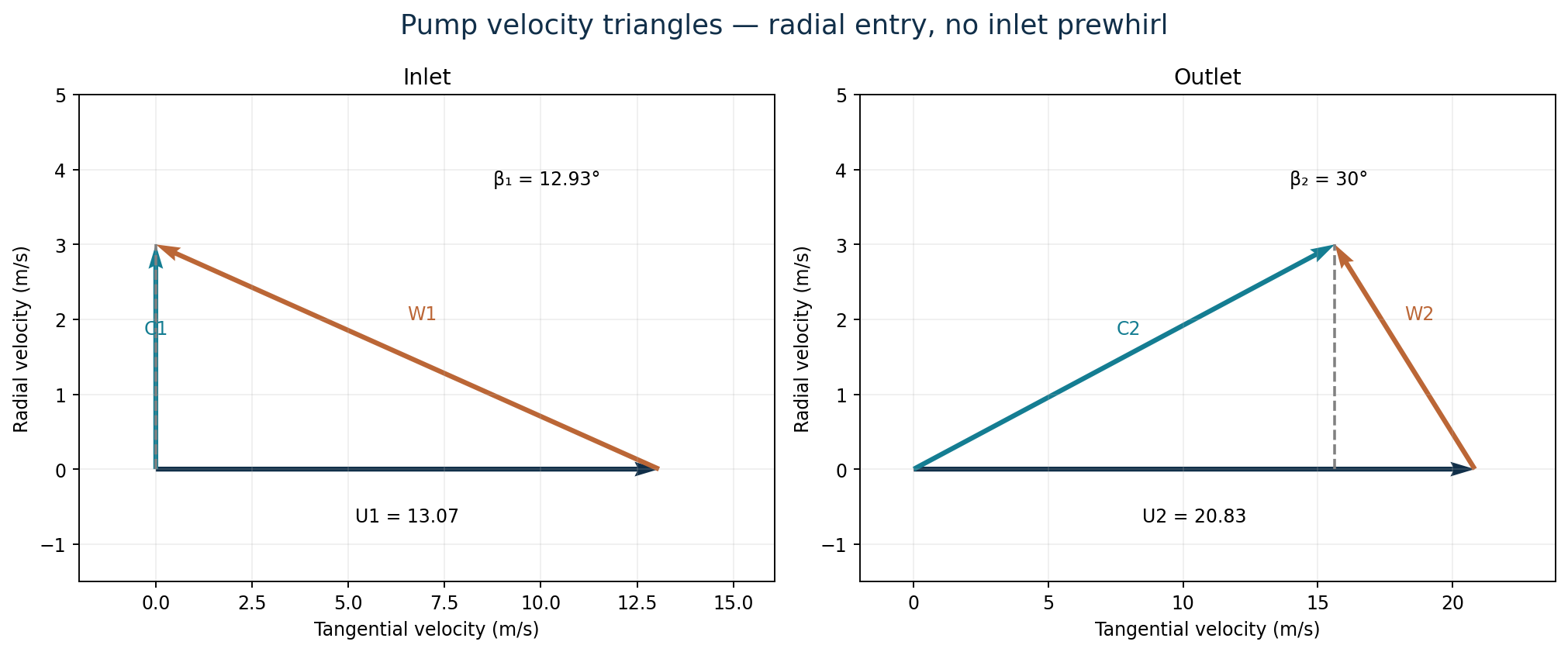
| Peripheral velocities | u₁ = π(0.160)(1560)/60 = 13.0690 m/s; u₂ = π(0.255)(1560)/60 = 20.8288 m/s. |
| (i) Inlet vane angle | tan β₁ = Vf/u₁ = 3/13.0690, hence β₁ = 12.928°. |
| Outlet whirl and Euler head | Vw₂ = u₂−Vf cot30° = 20.8288−3 cot30° = 15.6326 m/s. HE = u₂Vw₂/g = 33.1914 m. |
| Pipe velocities | Vs = Q/(πds²/4) = 0.055/[π(0.150)²/4] = 3.11236 m/s; Vd = 0.055/[π(0.100)²/4] = 7.00282 m/s. These differ from the impeller flow velocity. |
| Actual manometric head | Hm = [pd/(ρg)−ps/(ρg)] + (Vd²−Vs²)/(2g) + (zd−zs) = [18−(−4)] + (7.00282²−3.11236²)/(2×9.81) + 0 = 24.0057 m. |
| Useful hydraulic output | Phyd = ρgQHm = 1000(9.81)(0.055)(24.0057) = 12.9523 kW. |
| (ii) Overall efficiency | ηo = Phyd/Pshaft = 12.9523/22 = 0.588741 = 58.87%. |
| (iii) Manometric efficiency | ηman = Hm/HE = 24.0057/33.1914 = 0.723251 = 72.33%. |
If the pressure tappings have an elevation difference Δz, replace Hm by 24.0057 + Δz metres. No tapping elevation difference is supplied in the paper.
Question 3(a)
State Buckingham’s π theorem.
(2 marks)
Answer
If a dimensionally homogeneous physical relation contains n variables expressible using k independent fundamental dimensions, it can be rewritten as a relation among n−k independent dimensionless products, called π groups. The repeating variables must together span those k dimensions.
Question 3(b)
Differentiate between geometrical similarity and dynamical similarity.
(4 marks)
Answer
| Similarity | Meaning and example |
|---|---|
| Geometrical | The model and prototype have the same shape: every corresponding length has the same constant scale ratio, so corresponding angles are equal and relative roughness must also be scaled where relevant. |
| Dynamical | Ratios of corresponding forces are the same in model and prototype, together with geometrical and kinematic similarity. The relevant dimensionless force ratios must match: for example Re for viscous-dominated internal flow or Fr for gravity-controlled free-surface flow. Matching shape alone does not ensure this. |
Question 3(c)
The pressure difference ΔP in a pipe of diameter D and length L due to viscous flow depends on the velocity V, viscosity μ and density ρ. Using dimensional analysis, derive an expression for ΔP and hence express pressure head for viscous flow in terms of Reynold’s number.
(14 marks)
Answer
There are six variables ΔP, D, L, V, μ and ρ and three basic dimensions M, L and T, giving three π groups. Choose ρ, V and D as repeating variables. Assume a smooth pipe, or fixed relative roughness, since no roughness variable is specified.
| Quantity | Dimensions |
|---|---|
| ΔP | ML⁻¹T⁻² |
| ρ | ML⁻³ |
| V | LT⁻¹ |
| μ | ML⁻¹T⁻¹ |
| D and L | L |
| Step | Working |
|---|---|
| Pressure group | π₁ = ΔPρᵃVᵇDᶜ. M: 1+a = 0; T: −2−b = 0; L: −1−3a+b+c = 0. Hence a = −1, b = −2, c = 0 and π₁ = ΔP/(ρV²). |
| Viscosity group | π₂ = μρᵃVᵇDᶜ. M: 1+a = 0; T: −1−b = 0; L: −1−3a+b+c = 0. Thus π₂ = μ/(ρVD) = 1/Re. |
| Length group | π₃ = L/D, since both have dimension L. |
| General relation | ΔP/(ρV²) = F(1/Re, L/D), or ΔP = ρV² φ(Re,L/D). Therefore pressure-loss head h = ΔP/(ρg) = (V²/g)φ(Re,L/D). |
| Fully developed pipe flow | An additional physical result is that pressure loss is proportional to length. Define the Darcy factor fD by ΔP = fD(L/D)(ρV²/2). Thus h = fD(Re)(L/D)V²/(2g) for a smooth pipe. |
| Laminar specialisation | From Poiseuille flow ΔP = 32μLV/D² and μ = ρVD/Re. Substituting gives ΔP = (32/Re)(L/D)ρV². |
| Required laminar pressure head | h = (32/Re)(L/D)V²/g = (64/Re)(L/D)V²/(2g). Hence fD = 64/Re, or Fanning f = 16/Re when h = 4f(L/D)V²/(2g). |
Dimensional analysis alone cannot supply the number 64 or prove linear dependence on L; these follow from the fully developed laminar-flow equations. Turbulent flow requires an appropriate friction-factor relation.
Question 4(a)
Define the term entropy.
(2 marks)
Answer
Entropy S is a thermodynamic state property defined for a reversible heat transfer by dS = δQrev/T, where T is absolute temperature. Its SI unit is J/K; specific entropy s has units J/(kg·K). For an isolated system, total entropy cannot decrease, and it remains constant for a reversible process.
Question 4(b)
One kilogram of steam undergoes a reversible isothermal process from 20 bar and 250°C to a pressure of 30 bar. Determine the heat flow, stating whether it is supplied or rejected and sketch the process on a T-S diagram.
(5 marks)
Answer
Both end states are superheated: saturation temperatures at 20 and 30 bar are about 212.38°C and 233.86°C. Use superheated-steam properties, not ideal-gas entropy. IAPWS-IF97 values below are rounded to steam-table precision.

| Step | Working |
|---|---|
| State data | At 20 bar, 250°C: s₁ = 6.547418 kJ/(kg·K). At 30 bar, 250°C: s₂ = 6.289287 kJ/(kg·K). |
| Entropy change | ΔS = m(s₂−s₁) = 1(6.289287−6.547418) = −0.258132 kJ/K. |
| Reversible isothermal heat | Q = ∫T dS = TΔS = (250+273.15)(−0.258132) = −135.042 kJ. |
| Direction | Heat rejected = 135.04 kJ. The T–S path is horizontal at 523.15 K and moves towards lower entropy during compression. |
Question 4(c)
A four stroke SI engine has the compression ratio of 6 and swept volume of 0.18 m³. Pressure and temperature at the beginning of compression are 98 kN/m² and 25°C. (i) Calculate the pressure, volume and temperatures at all state points if heat supplied to it is 180 kJ/kg. (ii) Determine the entropy change, and efficiency of the otto cycle. Take Cp = 1 kJ/kgK and Cv = 0.71 kJ/kgK.
(13 marks)
Answer
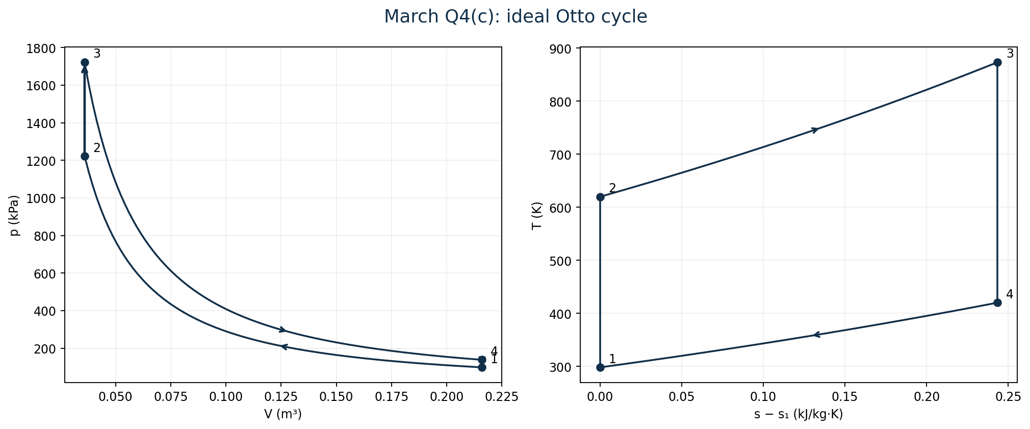
Use the ideal air-standard Otto cycle. Compression 1→2 and expansion 3→4 are reversible adiabatic; heat addition 2→3 and rejection 4→1 are at constant volume. Use the supplied specific heats consistently: γ = Cp/Cv = 1/0.71 = 1.408451 and R = Cp−Cv = 0.29 kJ/(kg·K).
| Step | Working |
|---|---|
| Cylinder volumes | r = V₁/V₂ = 6; Vs = V₁−V₂ = 0.18 m³. Thus V₂ = 0.18/(6−1) = 0.036 m³ and V₁ = 0.216 m³. V₃ = V₂; V₄ = V₁. |
| State 2: isentropic compression | T₂ = 298.15×6^(γ−1) = 619.828 K; p₂ = 98×6^γ = 1222.401 kPa. |
| State 3: constant-volume heating | T₃ = T₂ + qin/Cv = 619.828 + 180/0.71 = 873.349 K. p₃ = p₂T₃/T₂ = 1722.386 kPa. |
| State 4: isentropic expansion | T₄ = T₃/6^(γ−1) = 420.099 K; p₄ = p₃/6^γ = 138.084 kPa. |
| State | Pressure (kPa absolute) | Volume (m³) | Temperature (K) |
|---|---|---|---|
| 1 | 98.000 | 0.216 | 298.150 |
| 2 | 1222.401 | 0.036 | 619.828 |
| 3 | 1722.386 | 0.036 | 873.349 |
| 4 | 138.084 | 0.216 | 420.099 |
| Step | Working |
|---|---|
| Entropy during heat addition | Δs₂₃ = Cv ln(T₃/T₂) = 0.71 ln(873.349/619.828) = +0.243454 kJ/(kg·K). |
| Entropy during other processes | Δs₁₂ = Δs₃₄ = 0. Δs₄₁ = Cv ln(T₁/T₄) = −0.243454 kJ/(kg·K). |
| Total entropy change of working air | Over the complete cycle, Δscycle = 0, since the air returns to its initial state. If “entropy change” refers to heat addition, it is the positive value calculated above. |
| Mass and extensive entropy change | m = p₁V₁/(RT₁) = 98(0.216)/[0.29(298.15)] = 0.244820 kg. Thus ΔS₂₃ = mΔs₂₃ = 0.0596025 kJ/K; ΔScycle = 0. |
| Thermal efficiency | ηOtto = 1−1/r^(γ−1) = 1−1/6^0.408451 = 0.518980 = 51.898%. |
| Energy check | qout = Cv(T₄−T₁) = 86.5837 kJ/kg. wnet = 180−86.5837 = 93.4163 kJ/kg; wnet/qin = 51.898%. |
Question 5(a)
Explain how velocity compounding technique reduces speed of rotation in an impulse turbine.
(3 marks)
Answer
In velocity compounding, the full stage pressure drop is taken mainly in the nozzle, creating a high-velocity jet. Two or more moving blade rows then absorb this velocity in successive steps. Fixed guide blades between moving rows redirect the partly slowed steam into the next rotor row without an intended pressure drop. Each moving row extracts only part of the available kinetic energy, so a much lower blade speed can be used than for one moving row absorbing the whole velocity drop. All moving rows may be carried on the same shaft.
Question 5(b)
Show that the rate of work done, Ẇ, by a tangential flow on to a moving blade of an impulse turbine is given by Ẇ = ṁ Cb(Cai + Cae). Where ṁ = constant mass flow rate; Cai = absolute velocity at inlet; Cae = absolute velocity at exit; Cb = blade tangential speed.
(5 marks)
Answer
The printed “absolute velocity” labels must be interpreted as tangential (whirl) components for this power equation. For a general angled jet, the full absolute speed cannot replace its tangential component. Take the direction of blade motion as positive.
| Step | Working |
|---|---|
| Tangential momentum equation | Force on the blade Ft = ṁ(Cw,in−Cw,out), where Cw,out is signed. This is the reaction to the change in fluid tangential momentum. |
| Power | Blade power Ẇ = FtCb = ṁCb(Cw,in−Cw,out). This signed-difference form is general for equal inlet and outlet blade speeds. |
| Oppositely directed outlet whirl | If inlet whirl is positive with magnitude Cai and outlet whirl is negative with magnitude Cae, then Cw,in = Cai and Cw,out = −Cae. |
| Required expression | Ẇ = ṁCb[Cai−(−Cae)] = ṁCb(Cai+Cae). If the exit whirl is in the same direction as the inlet, use a difference of positive magnitudes instead. |
Question 5(c)
The velocity of steam at inlet to an impulse turbine is 1000 m/s, and the nozzle angle is 20°. The blade speed is 400 m/s and the blades are symmetrical. (i) Calculate the blade angle if the steam is to enter without shock. (ii) If the friction effects on the blade are negligible and there is a mass flow of 0.75 kg/s. Calculate the tangential force on the blades, the diagram power, axial thrust and the diagram efficiency.
(12 marks)
Answer
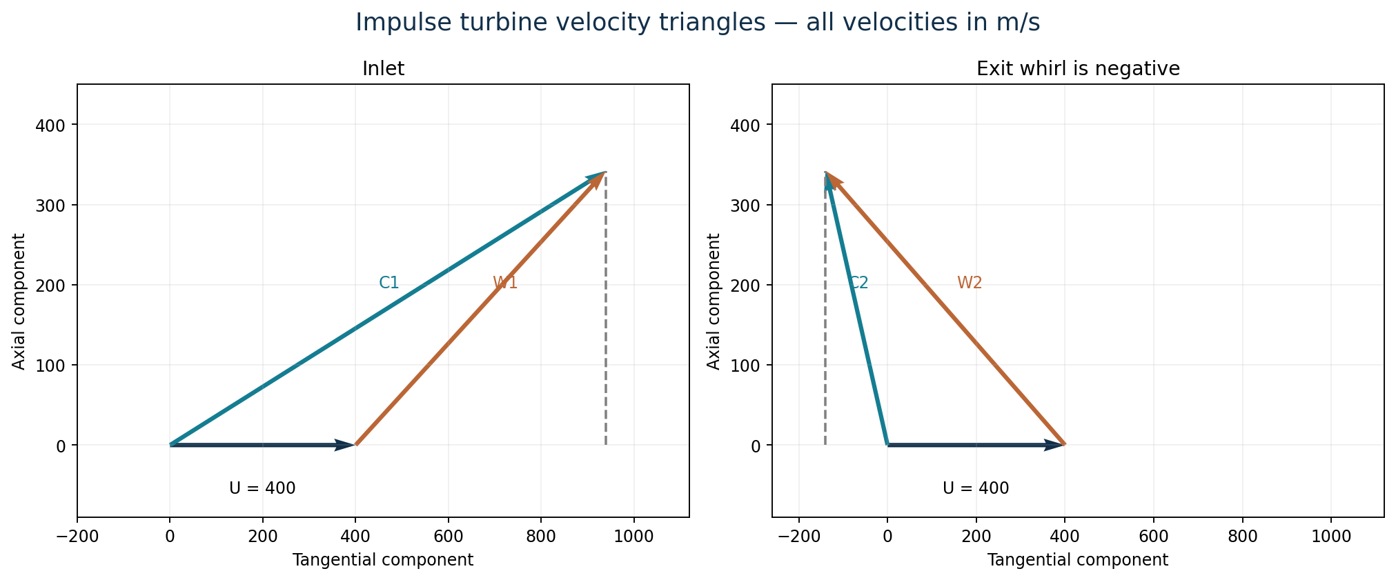
Measure the nozzle angle from the plane of rotation. Let C be absolute speed, W relative speed, U blade speed and β the blade angle from the tangent. Symmetric, frictionless blades give β₂ = β₁, W₂ = W₁ and equal inlet and exit axial components.
| Step | Working |
|---|---|
| Nozzle velocity components | Cw₁ = 1000 cos20° = 939.6926 m/s; Ca₁ = 1000 sin20° = 342.0201 m/s. |
| (i) Shockless entry angle | Wt₁ = Cw₁−U = 539.6926 m/s. β₁ = tan⁻¹[342.0201/539.6926] = 32.3637°. Symmetry gives β₂ = 32.3637°. |
| Exit whirl | For symmetric frictionless blades, Wt₂ = −Wt₁. Thus Cw₂ = U−(Cw₁−U) = 2U−Cw₁ = −139.6926 m/s. |
| (ii) Tangential force | Ft = ṁ(Cw₁−Cw₂) = 0.75[939.6926−(−139.6926)] = 809.539 N. |
| Diagram power | Pdiagram = FtU = 809.539(400) = 323,815.6 W = 323.816 kW. |
| Axial thrust | Fa = ṁ(Ca₁−Ca₂) = 0, since Ca₂ = Ca₁ for the stated symmetric, frictionless conditions. |
| Diagram efficiency | ηdiagram = Pdiagram/(½ṁC₁²) = 323,815.6/[0.5(0.75)(1000)²] = 0.863508 = 86.351%. |
Question 6(a)
A single stage, single acting compressor has a suction temperature and pressure T₁ and P₁ respectively. When delivery pressure is P₂, the mass flow rate of the air is ṁ, the compression index of air in the compressor is ‘n’. Using a P-V diagram, show that the work done per second to the compressor can be expressed as: Ẇ = [n/(n−1)]ṁRT₁{(P₂/P₁)^((n−1)/n) − 1}. Where n is specific gas constant.
(9 marks)
Answer
The final printed sentence contains a symbol error: n is the dimensionless polytropic index, as defined earlier in the question, and R is the specific gas constant. Use absolute pressures. Assume ideal-gas behaviour and reversible polytropic compression with exponent n ≠ 1. Work input to the compressor is positive.
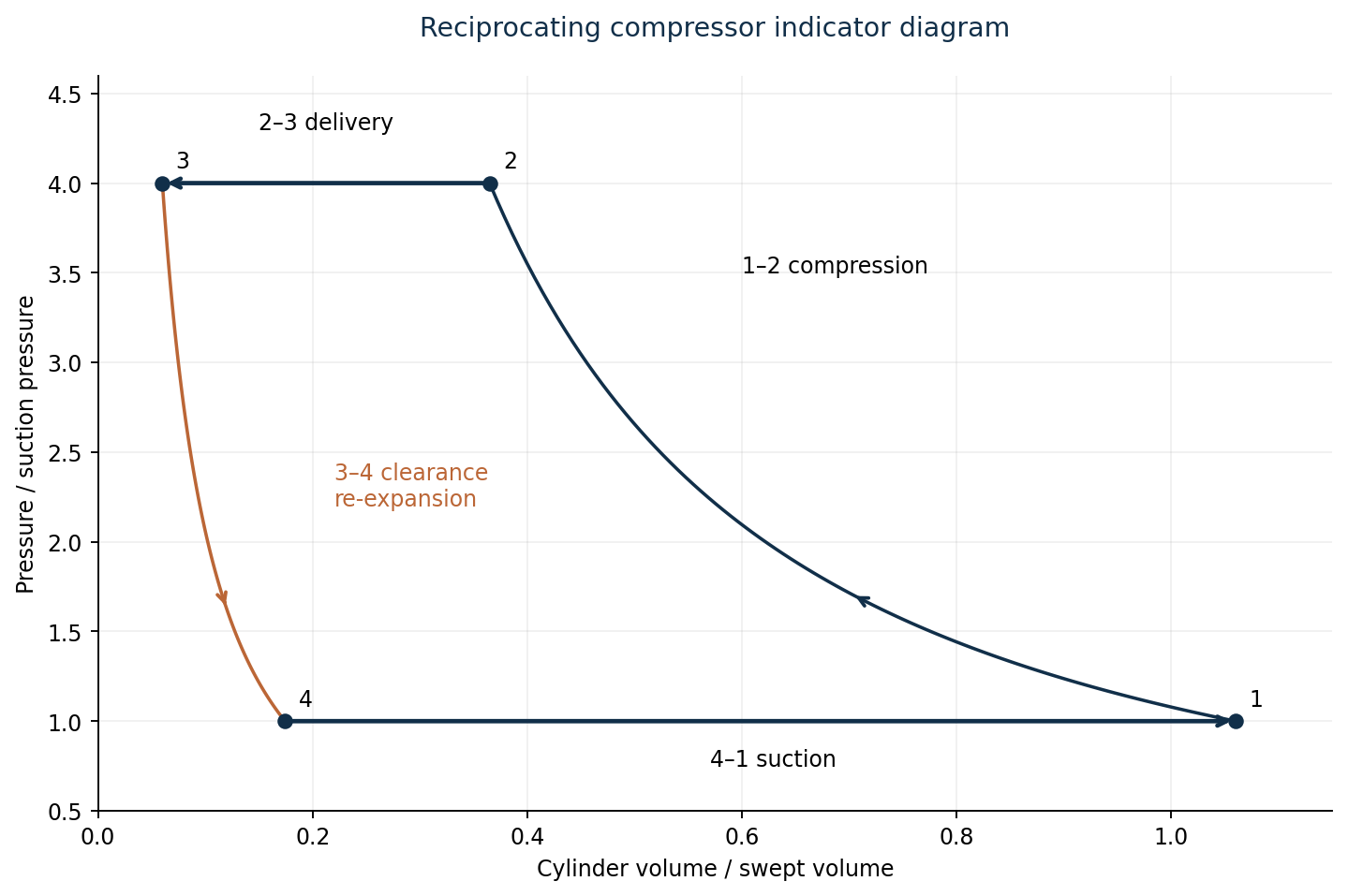
| Step | Working |
|---|---|
| Cylinder compression law | pvⁿ = constant, so v = v₁(p₁/p)^(1/n), with v denoting specific volume. |
| Include suction and delivery work | For a reversible compressor, total indicated input per unit fresh mass is w = ∫p₁ᵖ₂ v dp. This includes flow/suction/delivery work; using only −∫p dv for the closed compression stroke omits those contributions. |
| Integrate | w = v₁p₁^(1/n)∫p₁ᵖ₂ p^(−1/n)dp = [n/(n−1)]v₁p₁^(1/n)[p₂^((n−1)/n)−p₁^((n−1)/n)]. |
| Use the ideal-gas inlet relation | p₁v₁ = RT₁. Therefore w = [n/(n−1)]RT₁[(p₂/p₁)^((n−1)/n)−1]. |
| Convert specific work to power | Ẇ = ṁw = [n/(n−1)]ṁRT₁[(p₂/p₁)^((n−1)/n)−1], as required. |
| Isothermal limit | As n→1, w→RT₁ ln(p₂/p₁), so Ẇiso = ṁRT₁ ln(p₂/p₁). For equal compression and re-expansion laws, clearance changes the fresh intake capacity but not this work per unit fresh mass. |
Question 6(b)
A single stage reciprocating compressor takes in air at a pressure of 98 kN/m² and delivers at 560 kN/m², when running at a speed of 520 rev/min. The compressor has a cylinder bore of 200 mm, a stroke of 330 mm and a clearance volume of 5% of the swept volume. (i) Sketch the P-V diagram of the compressor. (ii) Calculate the volumetric efficiency, cycle power and isothermal efficiency.
(11 marks)
Answer
The source does not specify the compression/re-expansion index n. A unique numerical answer is therefore unavailable. The complete result is given below as a function of n, followed by a clearly labelled example. Assume single-acting operation as in Q6(a), absolute stated pressures, identical compression and re-expansion indices, no suction heating and no valve losses. Suction temperature is not required because power can be calculated from p₁V̇in.
| Step | Working |
|---|---|
| Swept and clearance volumes | Vs = (π/4)d²L = (π/4)(0.200)²(0.330) = 0.01036726 m³ per revolution. Vc = 0.05Vs = 0.000518363 m³; Vmax = 1.05Vs. |
| Pressure ratio | r = p₂/p₁ = 560/98 = 5.7142857. |
| Re-expansion volume | Clearance gas at p₂ and Vc expands to p₁ at V₄ = Vc r^(1/n). Fresh intake volume per revolution = Vmax−V₄. |
| Volumetric efficiency | ηv(n) = (Vmax−V₄)/Vs = 1 + C−C r^(1/n) = 1.05−0.05(5.7142857)^(1/n). |
| Fresh inlet volume rate | V̇in(n) = ηvVsN/60 = 0.08984955 ηv m³/s. |
| Indicated cycle power | Pind(n) = [n/(n−1)]p₁V̇in[r^((n−1)/n)−1] = 8.805256 ηv[n/(n−1)][5.7142857^((n−1)/n)−1] kW. |
| Ideal isothermal power at the same intake rate | Piso(n) = p₁V̇in ln r = 8.805256 ηv ln(5.7142857) kW. |
| Isothermal efficiency | ηiso(n) = Piso/Pind = ln r / {[n/(n−1)][r^((n−1)/n)−1]}. Use the continuous n = 1 limit for isothermal compression. |
| Assumed index n | Volumetric efficiency | Cycle power (kW) | Isothermal efficiency |
|---|---|---|---|
| 1 | 76.429% | 11.730 | 100.000% |
| 1.2 | 83.632% | 14.894 | 86.177% |
| 1.3 | 85.891% | 16.227 | 81.233% |
| 1.4 | 87.636% | 17.431 | 77.159% |
Illustration only: if n = 1.3 is specified by an instructor, ηv = 85.891%, indicated power = 16.227 kW and ηiso = 81.233%. The paper does not print n = 1.3, so these values must not be presented as unconditional answers. The different rows demonstrate why the missing index matters.
Question 7(a)
With the aid of a diagram, explain one method of improving the thermal efficiency of a gas turbine plant.
(4 marks)
Answer

Use regeneration. Pass the hot turbine exhaust through one side of a heat exchanger and the cooler compressor delivery air through the other. The compressed air enters the combustion chamber at a higher temperature, so less fuel heat is needed to reach the same turbine inlet temperature. Ideally compressor and turbine work are unchanged, while external heat input decreases, raising ηth = Wnet/Qin. Heat recovery is useful only when turbine exhaust is hotter than compressor delivery; excessive exchanger pressure losses can reduce the benefit.
Question 7(b)
A gas turbine plant having a compression ratio of 6:1 takes in air at a temperature of 24°C and a mass flow rate of 4 kg/s. The air is heated in a heat exchanger of thermal ratio 0.68 and is further heated in a combustion chamber to a maximum temperature of 850°C, before it is expanded in a power output turbine which also drives the compressor. If the isentropic efficiency of the compressor is 0.83. (i) Draw the plant and T-S diagram of the plant; (ii) Determine the power output; (iii) Calculate the thermal efficiency. Take γair = 1.4, Cp air = 1.005 kJ/kgK, Cp gas = 1.15 kJ/kgK, γgas = 1.4.
(16 marks)
Answer
Interpret 6:1 as the compressor pressure ratio. The question gives no turbine efficiency, so the numerical solution below assumes an isentropic turbine (ηt = 1), no component pressure drops, negligible fuel mass, equal 4 kg/s flow through compressor and turbine, and no mechanical losses. A real turbine efficiency below one would change both power and efficiency. Use the station labels in the plant diagram: 1, 2, r, 3, 4 and 6.

| Step | Working |
|---|---|
| Inlet and maximum temperatures | T₁ = 297.15 K; T₃ = 1123.15 K; aair = agas = (1.4−1)/1.4 = 0.285714. |
| Compressor | T₂s = T₁×6^a = 495.798 K. T₂ = T₁ + (T₂s−T₁)/0.83 = 536.485 K. |
| Assumed isentropic turbine | T₄ = T₃/6^a = 673.145 K. |
| Regenerator thermal ratio | ε = (Tr−T₂)/(T₄−T₂) = 0.68. Hence Tr = 536.485 + 0.68(673.145−536.485) = 629.414 K. |
| Regenerator heat balance | qreg = Cp,air(Tr−T₂) = 1.005(629.414−536.485) = 93.3938 kJ/kg. Since Cp differs on the two sides, T₆ = T₄−qreg/Cp,gas = 591.933 K, rather than subtracting the same temperature rise. |
| Specific compressor input | wc = Cp,air(T₂−T₁) = 1.005(536.485−297.15) = 240.531 kJ/kg. |
| Specific turbine output | wt = Cp,gas(T₃−T₄) = 1.15(1123.15−673.145) = 517.505 kJ/kg. |
| (ii) Net power output | wnet = wt−wc = 276.974 kJ/kg. Pnet = 4(276.974) = 1107.896 kW ≈ 1.108 MW. |
| Heat-input convention with different specific heats | Using the examination constant-property enthalpy model h = CpT on each stream and neglecting fuel mass: qin = h₃−hr = Cp,gas T₃−Cp,air Tr = 1.15(1123.15)−1.005(629.414) = 659.061 kJ/kg. |
| (iii) Thermal efficiency under this model | ηth = wnet/qin = 276.974/659.061 = 0.420255 = 42.026%. |
Model convention: if heat supplied is instead approximated as Cp,gas(T₃−Tr), the heat-input estimate is 567.796 kJ/kg and ηth = 48.780%. This is a different heat-input approximation when Cp,air ≠ Cp,gas; the solution above states its enthalpy convention explicitly. The paper supplies neither a combustion/fuel model nor a turbine efficiency, so the numerical thermal efficiency is conditional on these modelling choices.
For a specified turbine efficiency, replace the turbine temperature by T₄ = T₃−ηt[T₃−T₃/6^a], then recalculate Tr, wt, qin and ηth. The plant and T–S diagrams are schematic; they are not a common-fluid property chart for chemically different streams.