Fluid Mechanics and Thermodynamics — October/November 2022
KNEC Diploma in Mechanical Engineering — Module III. Paper code: 2502/304 (also 2501/304, 2503/304, 2508/304, 2509/304). Independent revision answers, not official KNEC marking schemes.
The supplied scan begins at printed page 2. It prints “Answer TWO questions” for Section A (Questions 1–3) and “Answer THREE questions” for Section B (Questions 4–7). All seven questions are answered for revision. Problematic head wording, friction-factor convention, compressor geometry, fuel-analysis data and pipe dimensions are retained and explained. Numerical properties and balances were independently checked.
Question 1(a)
With the aid of a sketch, explain the operation of a reciprocating pump.
(8 marks)
Answer
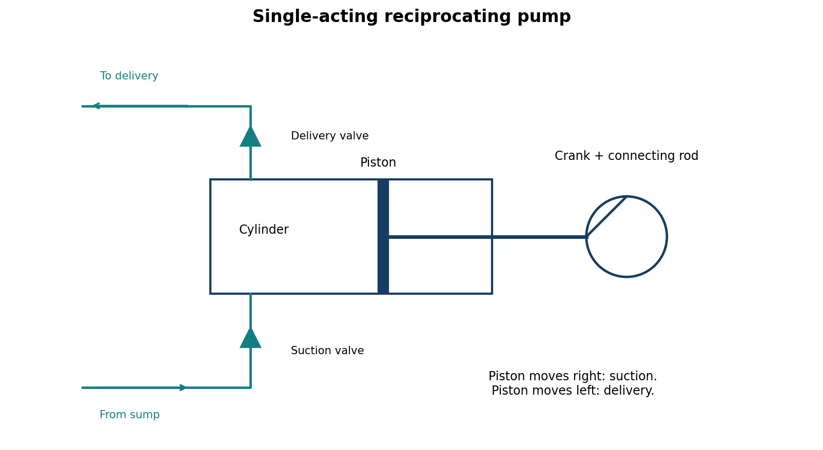
- The crank and connecting rod convert rotary input into reciprocating piston motion in the cylinder.
- During the suction stroke, increasing cylinder volume lowers its pressure below the suction-side pressure. The suction valve opens and liquid enters from the sump; the delivery valve remains closed.
- During the delivery stroke, decreasing cylinder volume raises pressure. The suction valve closes; when cylinder pressure exceeds delivery pressure the delivery valve opens and liquid is displaced into the delivery pipe.
- The non-return valves prevent reverse flow. In a single-acting pump there is one suction and one delivery stroke per revolution, so flow is pulsating. An air vessel may reduce discharge fluctuations.
The pump is a positive-displacement machine; it requires a safe discharge/pressure-relief arrangement and must not be driven against an unrelieved closed delivery.
Question 1(b)
A centrifugal pump impeller having an external and internal diameter of 480 mm and 240 mm respectively, is running at 1000 rpm. The rate of flow through the pump is 0.0576 m³/s and the velocity of flow is constant and equal to 2.4 m/s. The diameters of the suction and delivery heads are 6.2 m and 30.2 m respectively. If the power required to drive the pump is 23.3 kW and the outlet vane angle is 45°, determine the: (i) inlet vane angle; (ii) overall efficiency of the pump; (iii) manometric efficiency of the pump.
(12 marks)
Answer
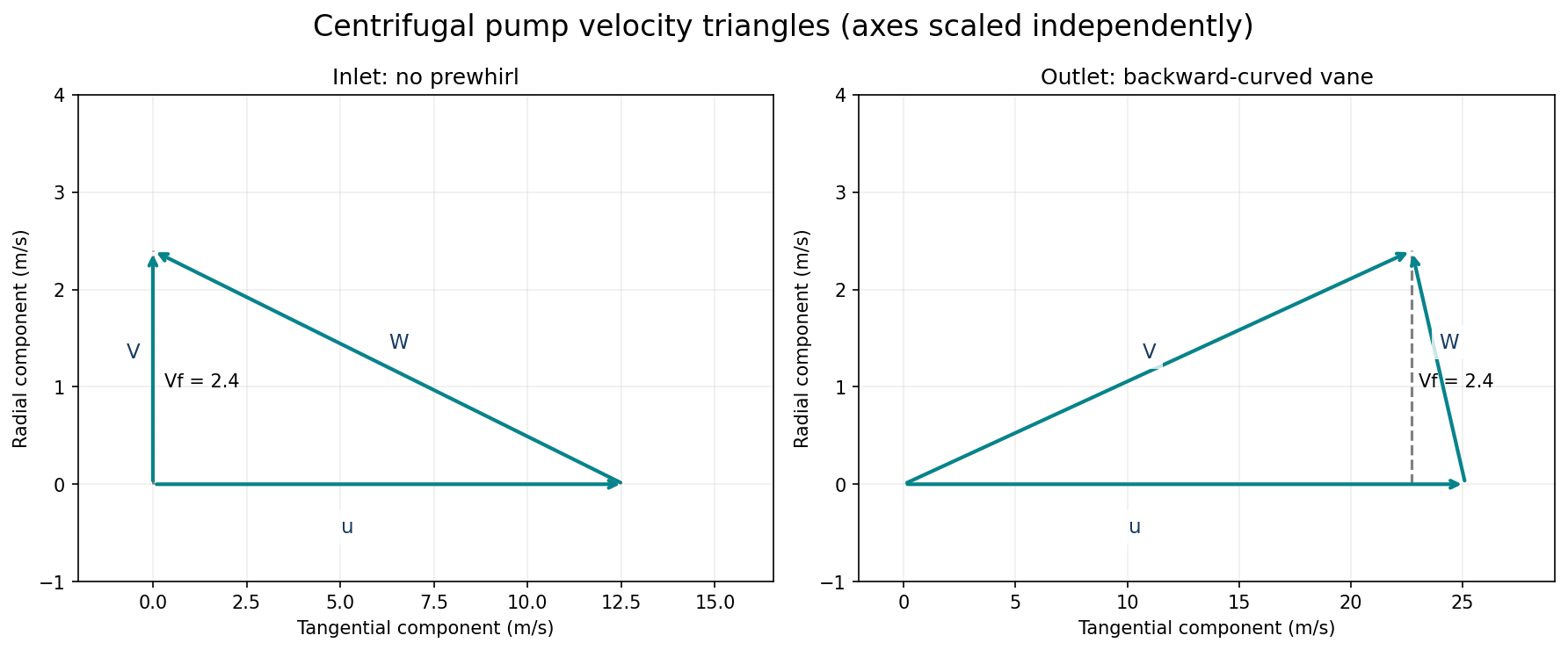
The wording “diameters of the suction and delivery heads” is inconsistent: the metre values are treated as heads. Assume a suction lift of 6.2 m and delivery elevation of 30.2 m, with other head terms neglected, so H = 36.4 m. Assume water (ρ = 1000 kg/m³), radial entry without prewhirl, and blade angles measured from the tangent.
| Step | Working |
|---|---|
| Peripheral speeds | u₁=πD₁N/60=π(0.240)(1000)/60=12.5664 m/s; u₂=25.1327 m/s. |
| I. Inlet vane angle | Vw₁=0; tanβ₁=Vf₁/u₁=2.4/12.5664 ⇒ β₁=10.8125°. |
| Outlet whirl | Vw₂=u₂−Vf₂ cotβ₂=25.1327−2.4 cot45°=22.7327 m/s. |
| Euler head | H_E=(u₂Vw₂−u₁Vw₁)/g=58.2402 m. |
| Water power | P_water=ρgQH=1000(9.81)(0.0576)(36.4)=20.5680 kW. |
| II. Overall efficiency | η_o=P_water/P_shaft=20.5680/23.3=0.88275=88.27%. |
| III. Manometric efficiency | η_man=H/H_E=36.4/58.2402=0.62500=62.50%. |
| Alternative head interpretation | If 6.2 m and 30.2 m are signed gauge/piezometric heads at the same datum, H=30.2−6.2=24 m instead. Then η_o=58.20% and η_man=41.21%. The scan does not resolve that ambiguity. |
Question 2(a)
Water from a large reservoir is discharged to the atmosphere through a 150 mm diameter pipe, 400 m long. The entry from the reservoir to the pipe is sharp and the outlet is 15 m below the surface level in the reservoir. Taking f = 0.01 in the Darcy formula, calculate the discharge.
(8 marks)
Answer
Use the Darcy–Weisbach friction factor f_D = 0.01 and a sharp-entry loss coefficient K_e = 0.5. Apply Bernoulli from the nearly stationary reservoir surface to the atmospheric pipe-exit jet. The exit velocity head is retained once, not counted again as an exit loss.
| Step | Working |
|---|---|
| Head balance | 15 = V²/(2g) + K_eV²/(2g) + f_D(L/D)V²/(2g). |
| Coefficient | 1+0.5+0.01(400/0.150)=28.1667. |
| Velocity | V=√[2(9.81)(15)/28.1667]=3.23242 m/s. |
| Area | A=π(0.150)²/4=0.0176715 m². |
| Discharge | Q=AV=0.0571215 m³/s ≈ 57.12 L/s. |
| Friction convention | Some texts write the Darcy head-loss formula as h_f=4fLV²/(2gD), using a Fanning-type f. If the printed 0.01 means that f, then f_D=0.04 and Q=0.0291488 m³/s. State the convention; do not apply the factor four twice. |
Question 2(b)(i)
Show by dimensional analysis F = ρϑ²L² φ{ρϑL/μ, Lg/ϑ²} where: F = drag force; ρ = mass density; ϑ = speed; L = length; μ = dynamic viscosity; g = gravitational acceleration.
(part of 2(b): 12 marks)
Answer
| Step | Working |
|---|---|
| Variables and dimensions | F:[MLT⁻²], ρ:[ML⁻³], ϑ:[LT⁻¹], L:[L], μ:[ML⁻¹T⁻¹], g:[LT⁻²]. Six variables and three primary dimensions give three independent Π groups. |
| Repeating variables | Choose ρ,ϑ,L. Let Π₁=FρᵃϑᵇLᶜ. |
| Force group | M:1+a=0; T:−2−b=0; L:1−3a+b+c=0. Thus a=−1,b=−2,c=−2 and Π₁=F/(ρϑ²L²). |
| Viscosity group | Π₂=μρᵃϑᵇLᶜ gives a=−1,b=−1,c=−1; Π₂=μ/(ρϑL). Use its reciprocal Re=ρϑL/μ. |
| Gravity group | Π₃=gρᵃϑᵇLᶜ gives a=0,b=−2,c=1; Π₃=gL/ϑ². |
| Functional relation | F/(ρϑ²L²)=φ(ρϑL/μ,gL/ϑ²). |
| Result | F=ρϑ²L²φ{ρϑL/μ,Lg/ϑ²}, as required. |
Question 2(b)(ii)
An aircraft of wing 10 m is required to fly at an average speed of 1000 km/hr. Its drag force is to be estimated from tests in water on a one third scale model. Determine the drag force on the full size aircraft, if that on the model is 900 N, taking the following: μ_air = 1.8 × 10⁻⁵ kg/ms, μ_water = 1.31 × 10⁻³ kg/ms, ρ_air = 1.225 kg/m³, ρ_water = 1000 kg/m³.
(part of 2(b): 12 marks)
Answer
Use the intended Reynolds-similarity estimate with geometrically similar model and prototype. Gravity/free-surface effects and compressibility are neglected. The printed length is treated as the characteristic wing length.
| Step | Working |
|---|---|
| Prototype and model | L_p=10 m; L_m=10/3 m; V_p=1000/3.6=277.7778 m/s. |
| Equal Reynolds numbers | ρ_pV_pL_p/μ_p=ρ_mV_mL_m/μ_m. |
| Model speed | V_m=V_p(L_p/L_m)(ρ_p/ρ_m)(μ_m/μ_p)=74.2940 m/s. |
| Reynolds number | Re=1.225(277.7778)(10)/(1.8×10⁻⁵)=1.89043×10⁸. |
| Equal drag coefficients | F_p/F_m=(ρ_p/ρ_m)(V_p/V_m)²(L_p/L_m)². |
| Answer under stated model | F_p=900(1.225/1000)(277.7778/74.2940)²(3²)=138.710 N. |
| Practical limitation | An aircraft at this speed can have significant compressibility effects. Reynolds equality alone does not reproduce Mach-number effects in a water test, and Reynolds and Froude similarity cannot generally both be imposed with these fluids/scale. Treat 138.710 N as the idealised examination estimate, not a reliable flight-drag prediction. |
Question 3(a)
Show that discharge Q of a fluid of dynamic viscosity μ, flowing under steady conditions through a horizontal circular pipe of diameter d, length L, with a mean velocity V, when the pressure difference between the ends is P, is given by the expression: Q = Pπd⁴/(128μL). Hence show that the difference in pressure P can be expressed as P = 32μLV/d². Where V = mean velocity.
(15 marks)
Answer
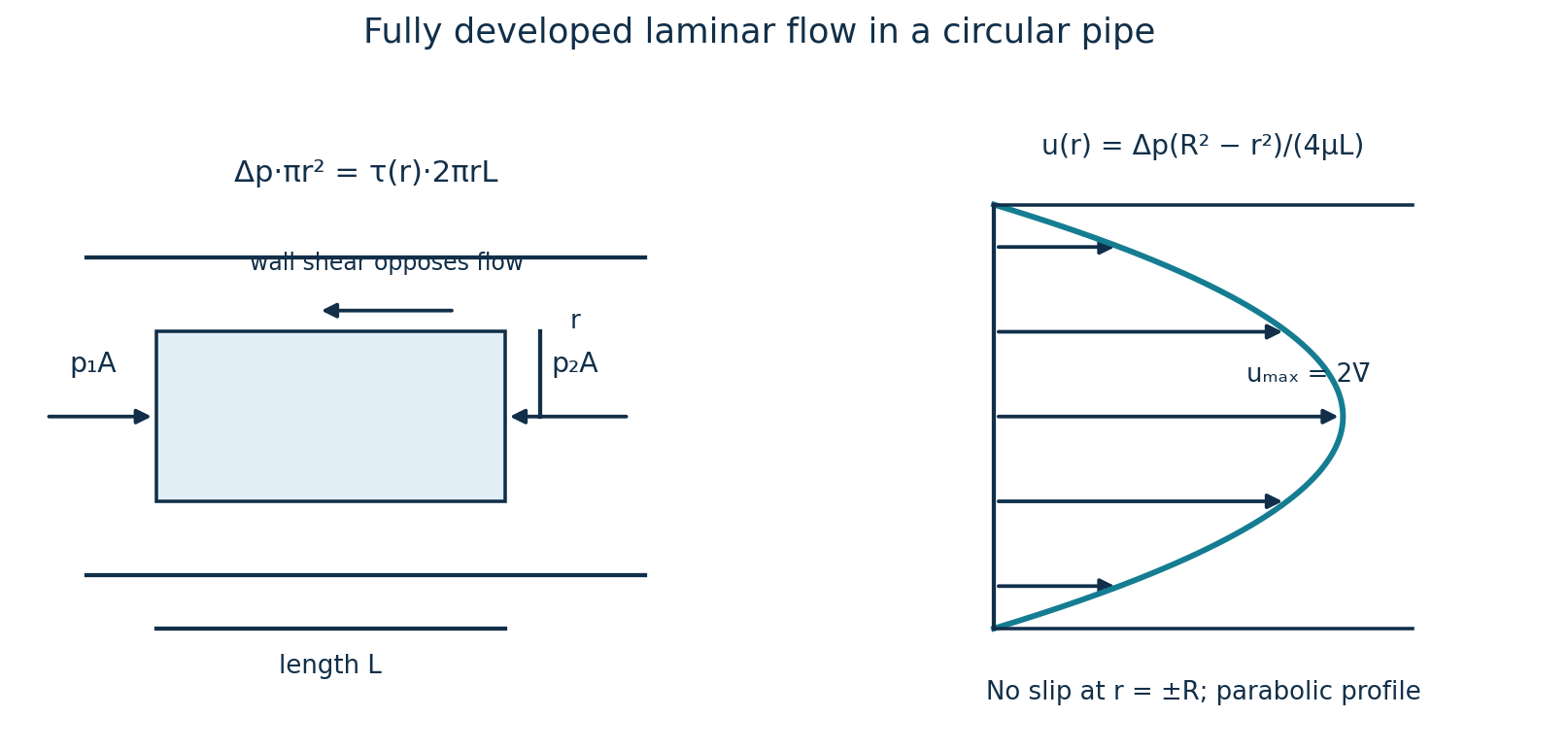
The derivation additionally requires incompressible, Newtonian, fully developed laminar flow in a straight circular pipe, with no slip at its wall. Steady flow alone is not sufficient.
| Step | Working |
|---|---|
| Force balance on radius r | Pπr²=τ(2πrL) ⇒ τ=Pr/(2L). |
| Newtonian shear | τ=−μ du/dr, where u decreases towards the wall. Thus du/dr=−Pr/(2μL). |
| Integrate | u(r)=−Pr²/(4μL)+C. Apply u(R)=0, R=d/2. |
| Velocity profile | u(r)=P(R²−r²)/(4μL). |
| Integrate across area | Q=∫₀ᴿu(r)2πrdr=[Pπ/(2μL)]∫₀ᴿ(R²r−r³)dr. |
| Discharge | Q=PπR⁴/(8μL)=Pπd⁴/(128μL). |
| Mean velocity | V=Q/(πd²/4)=Pd²/(32μL). |
| Pressure drop | P=32μLV/d², as required. |
Question 3(b)
Oil of viscosity 0.048 kg/ms flows through an 18 mm diameter pipe with a mean velocity of 0.3 m/s. Calculate: (i) the pressure drop which occurs over a length of 45 m; (ii) the velocity at 3 mm from the wall of the pipe.
(5 marks)
Answer
Use the fully developed laminar-flow relation from Question 3(a). Density is not supplied, so a numerical Reynolds check cannot be completed.
| Step | Working |
|---|---|
| Dimensions | d=0.018 m; R=0.009 m; L=45 m; μ=0.048 Pa·s; V=0.3 m/s. |
| I. Pressure drop | P=32μLV/d²=32(0.048)(45)(0.3)/(0.018)²=64,000 Pa=64.0 kPa. |
| Position | 3 mm from wall means r=9−3=6 mm from centre, not r=3 mm. |
| Velocity profile | u(r)=2V[1−(r/R)²]. |
| II. Local velocity | u=2(0.3)[1−(6/9)²]=0.333333 m/s. |
Question 4(a)
A cylinder contains 0.07 kg of fluid having a pressure of 1 bar, a volume of 0.06 m³ and a specific internal energy of 200 kJ/kg. After polytropic compression, the pressure and volume of the fluid are 9 bar and 0.0111 m³ respectively, and the specific internal energy is 270 kJ/kg. Determine the: (i) amount of work energy required for the compression; (ii) the quantity and direction of the energy flowing during the compression.
(8 marks)
Answer
Take pressures as absolute, W positive for work done by the fluid and Q positive into the fluid. For a closed system with negligible kinetic/potential changes, Q−W=ΔU.
| Step | Working |
|---|---|
| Polytropic index | p₁V₁ⁿ=p₂V₂ⁿ ⇒ n=ln(9/1)/ln(0.06/0.0111)=1.3021366. |
| Boundary work | W_by=(p₂V₂−p₁V₁)/(1−n), with pressure in kPa. |
| I. Work | W_by=[900(0.0111)−100(0.06)]/(1−1.3021366)=−13.20595 kJ. Thus work required on fluid = 13.20595 kJ. |
| Internal-energy rise | ΔU=m(u₂−u₁)=0.07(270−200)=4.9 kJ. |
| Heat | Q=ΔU+W_by=4.9−13.20595=−8.30595 kJ. |
| II. Direction | 8.30595 kJ of heat flows out of the fluid to its surroundings during compression. |
Question 4(b)
A two-stage, single-acting reciprocating compressor takes in air at a rate of 6 m³/min. The intake pressure and temperature are 1.013 bar and 15 °C respectively and the air is compressed to 75 bar. The compression index is 1.25 and the compressor runs at 300 rpm. The mechanical efficiency is 80% and the volumetric efficiency is 85%. The ratio of the stroke to bore is 1:1 for both stages. The intermediate pressure is ideal and inter cooling is complete. Determine for the compressor the: (i) indicated power; (ii) motor power; (iii) diameter of the bore in both stages. Assume the stroke is the same in both stages.
(12 marks)
Answer
The geometry statements conflict: equal stroke and stroke/bore=1 in both stages would require equal bores, whereas the high-pressure stage needs a smaller swept volume. Power is unaffected. For the principal geometry answer, take a square low-pressure cylinder and the stated common stroke, allowing the high-pressure stroke/bore ratio to differ; then show the alternative where both cylinders are square.
| Step | Working |
|---|---|
| Flow and pressure | Q₁=6/60=0.1000 m³/s; p₁=101300 Pa; p₃=75 bar absolute; n=1.25. |
| Ideal intermediate pressure | p_i=√(p₁p₃)=√(1.013×75)=8.716364 bar. Equal stage pressure ratio r_s=p_i/p₁=8.604505. |
| I. Indicated power | P_i=2[n/(n−1)]p₁Q₁[r_s^((n−1)/n)−1]. |
| Substitution | P_i=2(1.25/0.25)(101300)(0.1)[8.604505^0.2−1]=54.4954 kW. |
| II. Motor power | P_motor=P_i/η_mech=54.4954/0.80=68.1192 kW. |
| LP swept-volume rate | Q_s,LP=Q₁/η_v=0.1/0.85=0.117647 m³/s. Single acting: Q_s=(πD²/4)L(N/60). |
| Square LP cylinder | Set L=D_LP: D_LP³=4Q₁/[π η_v(N/60)] ⇒ D_LP=0.310580 m. |
| Common stroke | L_LP=L_HP=0.310580 m. Complete intercooling gives Q_HP=Q₁p₁/p_i=0.01162182 m³/s. |
| III. HP bore, common stroke | D_HP=√[4Q_HP/(π η_v L_HP(N/60))]=0.105879 m. |
| Principal geometry answer | LP bore=310.58 mm; HP bore=105.88 mm; common stroke=310.58 mm. This cannot also satisfy L_HP/D_HP=1. |
| Alternative: both cylinders square | D_HP=L_HP=[4Q_HP/(π η_v(N/60))]^(1/3)=151.565 mm. LP remains 310.58 mm; the strokes are then unequal. No geometry satisfies all the printed statements simultaneously. |
Question 5(a)
In a steam engine, the steam at the beginning of the expansion process is 7 bar, dryness fraction 0.95. The expansion process follows the law PV^1.1 = c, down to a pressure of 0.34 bar. Calculate the: (i) work done per kg of steam during the expansion; (ii) heat flow per kg of steam to or from the cylinder walls during the expansion.
(8 marks)
Answer
Use absolute pressures, a closed-system expansion and steam-table properties from IAPWS-IF97. Mixture relations retain the saturated-liquid volume. Values may vary slightly with table rounding.
| State/property | Value |
|---|---|
| At 7 bar, x₁=0.95 | v₁=0.2591812 m³/kg; u₁=2478.042 kJ/kg. |
| At 0.34 bar saturated liquid | v_f₂=0.00102396 m³/kg; u_f₂=301.3629 kJ/kg. |
| At 0.34 bar saturated vapour | v_g₂=4.6498179 m³/kg; u_fg₂=2170.0541 kJ/kg. |
| Step | Working |
|---|---|
| Final volume | p₁v₁^1.1=p₂v₂^1.1 ⇒ v₂=v₁(p₁/p₂)^(1/1.1)=4.0532434 m³/kg. |
| Final dryness | x₂=(v₂−v_f₂)/(v_g₂−v_f₂)=0.871671. |
| Final internal energy | u₂=u_f₂+x₂u_fg₂=2192.9364 kJ/kg. |
| I. Expansion work | w=(p₁v₁−p₂v₂)/(n−1)=[700(0.2591812)−34(4.0532434)]/0.1=436.1656 kJ/kg. |
| II. Heat flow | q=(u₂−u₁)+w=2192.9364−2478.0420+436.1656=151.0600 kJ/kg. |
| Direction | Heat enters the steam from the cylinder walls. A polytropic expansion is not automatically adiabatic. |
Question 5(b)
The nozzles of a simple impulse turbine are inclined at an angle of 20° to the direction of the path of the moving blades. The steam leaves the nozzle at 450 m/s and the blade speed is 180 m/s. There is no axial thrust on the blades and the velocity of the steam is reduced by 15% in passing over the blades. Determine the: (i) blade angles; (ii) power developed for a steam flow of 3.5 kg/s; (iii) kinetic energy of the steam finally leaving the wheel.
(12 marks)
Answer
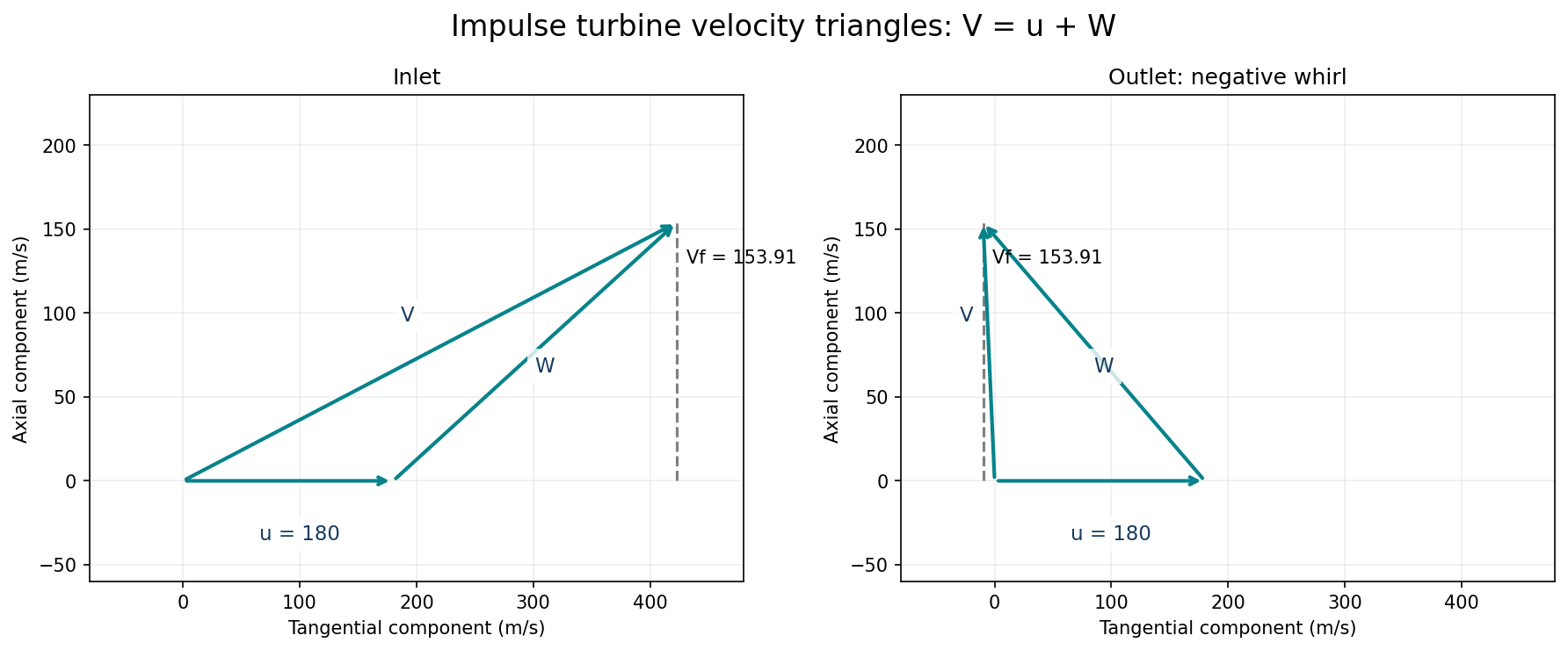
Interpret the 15% reduction as a reduction of relative velocity across the moving blades: W₂=0.85W₁. For an ideal impulse row with negligible axial pressure-force difference, no axial thrust means equal inlet/outlet axial velocity. Blade angles below are acute angles to the relevant tangents; use signed outlet whirl.
| Step | Working |
|---|---|
| Inlet components | Vw₁=450cos20°=422.8617 m/s; Vf=450sin20°=153.9091 m/s. |
| Relative inlet | W₁=√[(Vw₁−u)²+Vf²]=287.5236 m/s. |
| I. Inlet blade angle | β₁=tan⁻¹[Vf/(Vw₁−u)]=32.3637°. |
| Relative outlet magnitude | W₂=0.85W₁=244.3950 m/s. |
| Outlet relative tangential component | B=√(W₂²−Vf²)=189.8445 m/s, directed opposite blade motion. |
| Outlet angle | β₂=tan⁻¹(Vf/B)=39.0321°. |
| Signed outlet whirl | Vw₂=u−B=180−189.8445=−9.8445 m/s. |
| II. Power | P=ṁu(Vw₁−Vw₂)=3.5(180)[422.8617−(−9.8445)]=272.6049 kW. |
| Exit absolute speed | V₂=√(Vw₂²+Vf²)=154.2236 m/s. |
| III. Specific exit kinetic energy | V₂²/2=11,892.457 J/kg=11.8925 kJ/kg. |
| Exit kinetic-energy rate | For ṁ=3.5 kg/s: ṁV₂²/2=41.6236 kW. Total energy requires a stated mass or time; these two forms resolve the wording. |
Question 6(a)
An ultimate analysis of a fuel gave the following: C = 70%, H₂ = 5%, O₂ = 12%, N₂ = 2% and Ash = 10%. Determine the: (i) stoichiometric air fuel ratio; (ii) air fuel ratio; (iii) volumetric analysis of the dry products in (a)(ii) above. Take the atomic masses as C = 12, H = 1, O = 16, N = 14.
(10 marks)
Answer
The supplied percentages sum to 99%, and no excess-air percentage is printed. Retain the stated masses on a nominal 1 kg fuel basis without inventing the missing 1%. Assume complete combustion and dry air of 21 mol% O₂ and 79 mol% N₂. An actual air/fuel ratio is not uniquely calculable without an excess-air condition.
| Step | Working |
|---|---|
| Oxygen for carbon | m_O₂,C=(32/12)(0.70)=1.866667 kg/kg nominal fuel. |
| Oxygen for hydrogen | m_O₂,H=8(0.05)=0.400000 kg/kg. |
| Credit fuel oxygen | m_O₂,st=1.866667+0.400000−0.120000=2.146667 kg/kg. |
| Oxygen in kmol | n_O₂,st=2.146667/32=0.06708333 kmol/kg. |
| I. Stoichiometric air/fuel | A_st=n_O₂,st[32+(79/21)28]=9.212778 kg air/kg nominal fuel. |
| II. Actual air/fuel | Let λ=actual air/stoichiometric air. Then A_actual=9.212778λ kg/kg. No unique numerical λ is supplied. |
| Products, kmol/kg | CO₂=0.70/12=0.05833333; N₂=λ(0.06708333)(79/21)+0.02/28=0.25236111λ+0.000714286; residual O₂=0.06708333(λ−1). |
| Dry total for λ≥1 | n_dry=0.05833333+0.25236111λ+0.000714286+0.06708333(λ−1). |
| III. Dry volume percentages | CO₂%=100(0.05833333)/n_dry; N₂%=100(0.25236111λ+0.000714286)/n_dry; O₂%=100[0.06708333(λ−1)]/n_dry. |
| Conditional stoichiometric case λ=1 | Air/fuel=9.212778; dry products CO₂=18.7321%, N₂=81.2679%, O₂=0%. These are conditional, not an invented actual-excess-air result. |
If the exercise is renormalised to a 100% fuel basis, every listed fuel mass must be divided by 0.99, making A_st≈9.30584 kg/kg; the stoichiometric dry volume percentages remain unchanged. The unassigned 1% composition could affect a real analysis.
Question 6(b)
A 50 mm pipe of 800 mm internal diameter and 950 mm external diameter and a thermal conductivity of 45 W/mK, is insulated with two successive layers. The pipe is in contact with a 35 mm thick layer of asbestos with a thermal conductivity of 0.11 W/mK. The asbestos is in turn covered by a 15 mm thick magnesia of thermal conductivity 0.067 W/mK. The inside and outside transfer coefficients are 290 W/m²K and 7.0 W/m²K respectively. Determine the rate of heat loss per metre length, if the steam is at a temperature of 350 °C and the ambient temperature is 24 °C.
(10 marks)
Answer
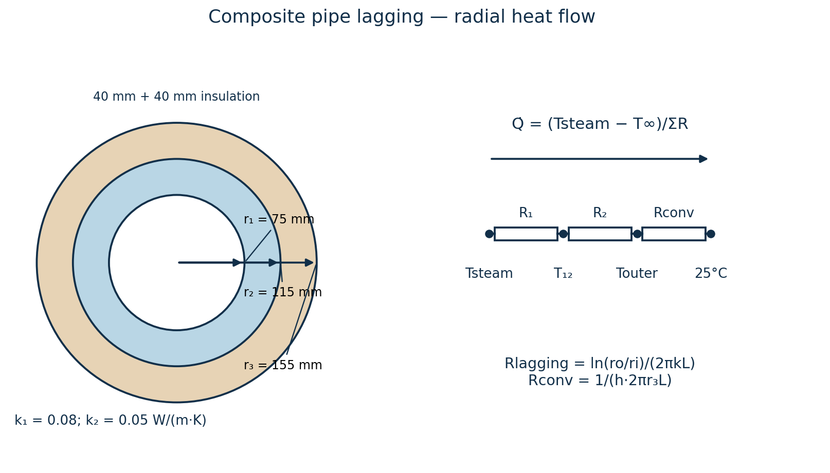
The opening “50 mm pipe” conflicts with the explicit 800/950 mm diameters. Retain those explicit diameters for the main calculation; do not silently substitute 80/95 mm. The named historical insulation is retained only as printed data, not recommended as a material.
| Step | Working |
|---|---|
| Radii for L=1 m | r₁=0.400 m; r₂=0.475 m; r₃=0.475+0.035=0.510 m; r₄=0.510+0.015=0.525 m. |
| Internal convection | R_i=1/(h_i2πr₁L)=0.00137203 K/W. |
| Pipe conduction | R_p=ln(r₂/r₁)/(2πk_pL)=0.000607796 K/W. |
| First insulation | R_a=ln(r₃/r₂)/(2πk_aL)=0.10286607 K/W. |
| Second insulation | R_m=ln(r₄/r₃)/(2πk_mL)=0.06885835 K/W. |
| External convection | R_o=1/(h_o2πr₄L)=0.04330747 K/W. |
| Total | R_total=0.21701171 K/W; ΔT=350−24=326 K. |
| Heat loss | Q/L=326/0.21701171=1502.223 W/m≈1.502 kW/m. |
Question 7(a)
1 kg of steam at 20 bar, dryness fraction 0.9, is heated reversibly at constant pressure to a temperature of 300 °C. Determine the: (i) heat supplied; (ii) change in entropy; (iii) show the process on a T.S diagram, indicating the area which represents the heat flow.
(8 marks)
Answer
Use 20 bar absolute and IAPWS-IF97 properties. The final state is superheated, so its properties come from a superheated table, not the saturated-steam line.
| State | h (kJ/kg) | s (kJ/kg K) |
|---|---|---|
| 20 bar, x=0.9 | 2609.4079 | 5.9499503 |
| 20 bar, 300 °C | 3024.2519 | 6.7685153 |
| Step | Working |
|---|---|
| Initial state | h₁=h_f+0.9h_fg; s₁=s_f+0.9s_fg at 20 bar. Saturation temperature ≈212.3845 °C. |
| I. Heat supplied | Q=m(h₂−h₁)=1(3024.2519−2609.4079)=414.8440 kJ. |
| II. Entropy rise | ΔS=m(s₂−s₁)=0.818565 kJ/K. |
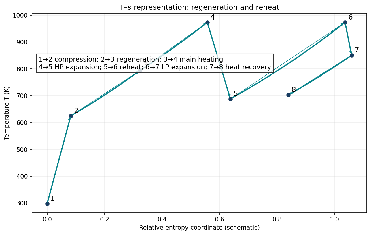
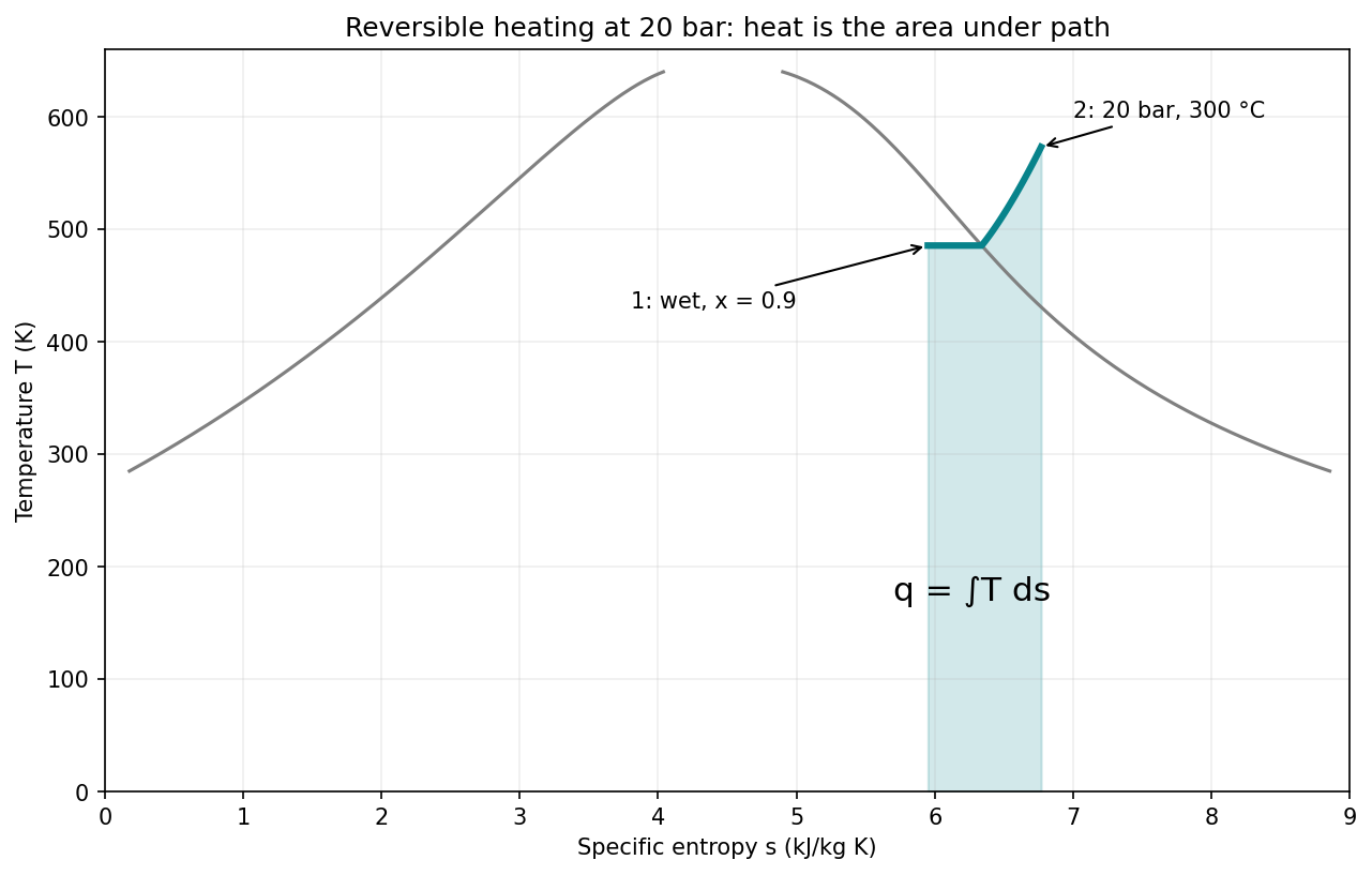
| III. T–s representation | First finish evaporation along the horizontal 20-bar saturation-temperature line; then follow the rising constant-pressure superheat path to 300 °C. |
| Heat area | For the reversible path, q=∫T ds; the shaded area under the path represents heat input. T must be in kelvin. |
Question 7(b)
In an open gas turbine plant, the air from the air compressor passes through a heat exchanger where it is heated by the exhaust gases from the low pressure (L.P.) turbine. The high pressure (HP) turbine drives the compressor only. The exhaust gases from the H.P. turbine passes through the L.P. combustion chamber, and then into the L.P. turbine, which drives an external load. Given the following data: Over pressure ratio = 10:1; isentropic efficiency of the compressor = 0.85; isentropic efficiency of the H.P. turbine = 0.86; isentropic efficiency of the L.P. turbine = 0.88; heat exchanger effectiveness = 0.75; temperature of the gases entering the H.P. turbine = 700 °C; temperature of the gases entering the L.P. turbine = 700 °C; atmospheric pressure and temperature are 1.013 bar and 25 °C respectively. Taking the specific heat capacity at constant pressure for air and gases as 1.005 kJ/kgK and 1.15 kJ/kgK, the index of compression and expansion as 1.4 and 1.33 for air and gases respectively, sketch the plant and T.S diagrams and hence calculate the: (i) pressure of the gases entering the L.P. turbine; (ii) overall thermal efficiency.
(12 marks)
Answer
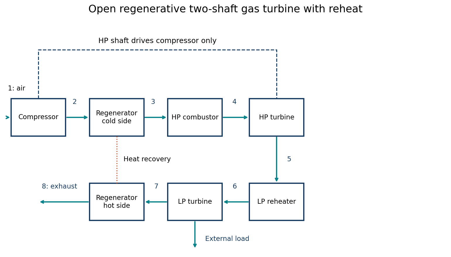
Interpret “Over pressure ratio” as overall compressor pressure ratio 10:1. Neglect pressure losses, fuel mass relative to air mass, and shaft/mechanical losses. Use the usual constant-cp examination model, c_pa=1.005 for compressor work and c_pg=1.15 for turbine and combustion temperature-rise calculations. Heat-exchanger effectiveness is the cold-side temperature effectiveness.
| Step | Working |
|---|---|
| State numbering | 1 compressor inlet; 2 outlet; 3 after regenerator; 4 HP-turbine inlet; 5 HP outlet; 6 after reheater/LP inlet; 7 LP outlet; 8 stack after regenerator. |
| Known temperatures | T₁=298.15 K; T₄=T₆=973.15 K; p₂=p₄=10.13 bar; p₇=p₁=1.013 bar. |
| Isentropic compression | T₂s=T₁(10)^[(1.4−1)/1.4]=575.6375 K. |
| Actual compressor | T₂=T₁+(T₂s−T₁)/0.85=624.6059 K. w_c=c_pa(T₂−T₁)=328.0882 kJ/kg. |
| HP shaft balance | c_pg(T₄−T₅)=w_c ⇒ T₅=973.15−328.0882/1.15=687.8559 K. |
| HP isentropic outlet | η_HP=(T₄−T₅)/(T₄−T₅s) ⇒ T₅s=641.4127 K. |
| I. LP-inlet pressure | p₅=p₄(T₅s/T₄)^[1.33/(1.33−1)]=1.887793 bar. With no reheater pressure loss, p₆=p₅. |
| LP isentropic outlet | T₇s=T₆(p₇/p₆)^[(1.33−1)/1.33]=833.8765 K. |
| Actual LP outlet | T₇=T₆−0.88(T₆−T₇s)=850.5893 K. |
| Regenerator cold outlet | T₃=T₂+0.75(T₇−T₂)=794.0935 K; regeneration is possible because T₇>T₂. |
| Main-combustor heat | q_HP=c_pg(T₄−T₃)=205.9150 kJ/kg. |
| Reheat input | q_LP=c_pg(T₆−T₅)=328.0882 kJ/kg. |
| Net external work | HP output is consumed by compressor, so w_net=c_pg(T₆−T₇)=140.9448 kJ/kg. |
| II. Overall thermal efficiency | η_th=w_net/(q_HP+q_LP)=140.9448/(205.9150+328.0882)=0.263940≈26.394%. |
| Regenerator energy check | c_pa(T₃−T₂)=c_pg(T₇−T₈) ⇒ T₈=702.4719 K. This internal recovered heat is not added to external heat input. |