Control Systems and Instrumentation — October/November 2022
KNEC Diploma in Mechanical Engineering — Module III. Paper code: 2501/302; 2503/302; 2508/302; 2509/302.
Questions are transcribed from the supplied examination paper. The independent revision answers are not official KNEC marking schemes. All 8 questions, including optional questions, are answered.
The supplied scan starts at printed page 2; its cover instructions are absent. Sections A (Questions 1–4) and B (Questions 5–8) each state “Answer at least TWO questions from this section.” All eight questions are answered for revision.
Printed source issues are explained beside the answers: the RLC ratios use Vin(c), “2-way” valve terminology does not specify a complete exhaust circuit, and Q6(b) assigns metres to strain. Bridge balance, resistance-change direction and output polarity are stated explicitly.
Question 1(a)
Differentiate between each of the following with reference to control systems: (i) man-made systems and natural systems; (ii) open-loop systems and hybrid systems.
(4 marks)
Answer
| Pair | First term | Second term |
|---|---|---|
| (i) | A man-made system is deliberately designed and assembled to perform a function, for example a motor-speed controller. | A natural system occurs in nature, for example biological regulation of body temperature. |
| (ii) | An open-loop system does not use its measured output to correct its control action; for example a timed heater without temperature feedback. | A hybrid system combines continuous dynamics with discrete states/events, for example continuous tank-level change with an on/off pump. |
Open-loop and hybrid describe different properties: a hybrid system can itself operate with or without feedback. They are not mutually exclusive alternatives.
Question 1(b)
With the aid of a labelled block diagram, describe the elements of a feedback control system.
(8 marks)
Answer
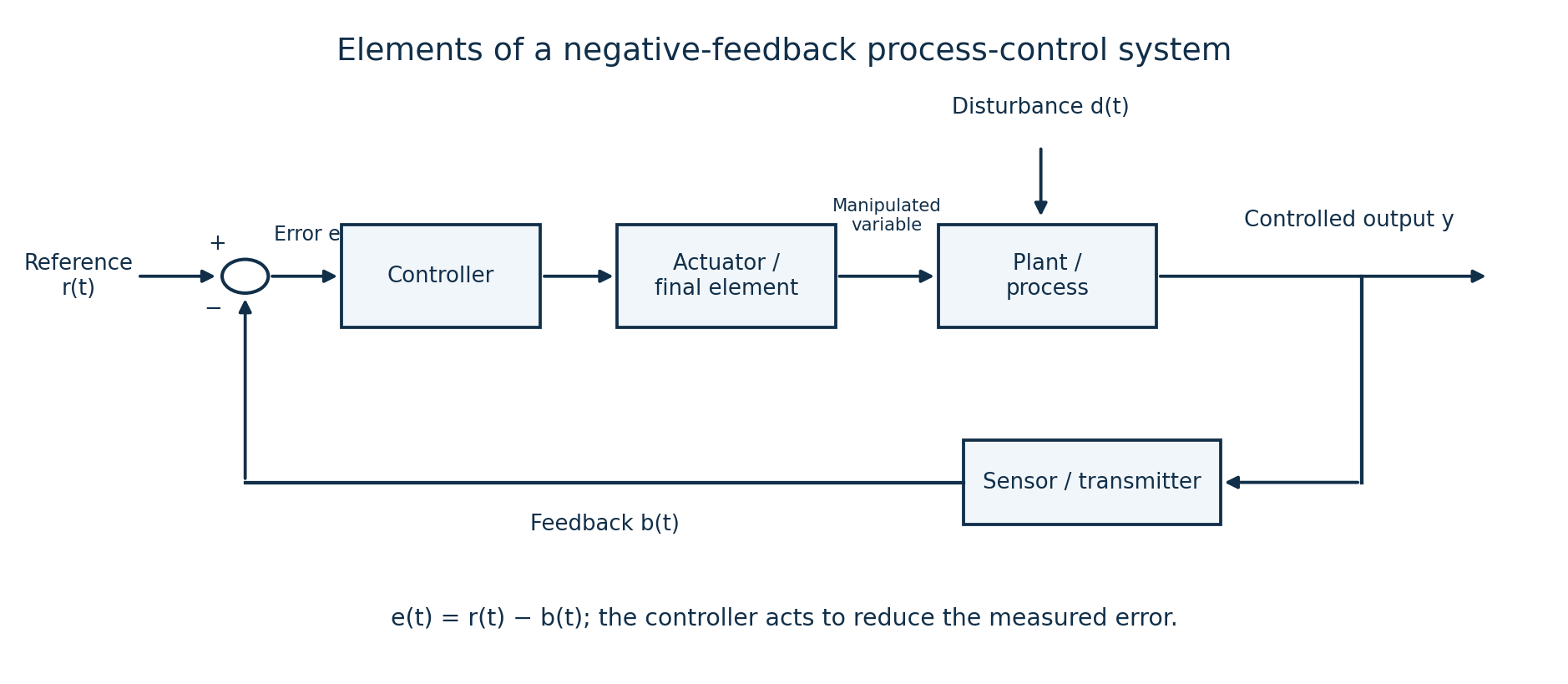
| Element or signal | Function |
|---|---|
| Reference/set-point r | Specifies the desired output. |
| Error detector/comparator | Subtracts the feedback signal b from the reference to produce e = r−b. |
| Controller | Processes the error according to its control law and issues a correcting command. |
| Actuator/final control element | Converts the command and supplied energy into a physical input, such as valve opening or motor torque. |
| Plant/process | The physical system being controlled. |
| Controlled output y | The actual process condition being regulated. |
| Sensor/transmitter | Measures the output and converts it into a suitable feedback signal. |
| Feedback path | Returns the measured signal to the comparator so departures from the reference can be corrected. |
Question 1(c)
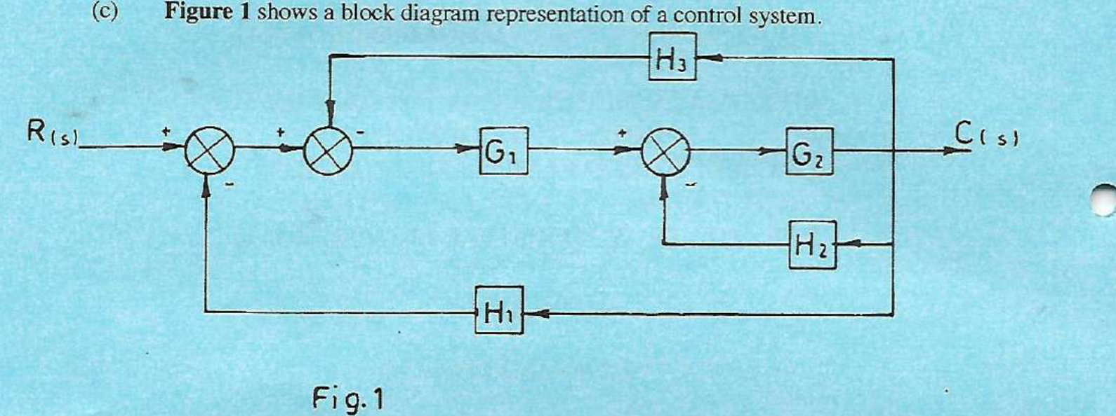
Figure 1 shows a block diagram representation of a control system. Determine the: (i) equivalent canonical form; (ii) closed-loop transfer function.
(8 marks)
Answer
Retain all three negative feedback signs in the printed diagram. H₁ and H₃ both return C(s) to summing points before G₁; H₂ returns C(s) to the summing point immediately before G₂. Use zero initial conditions.
| Step | Working |
|---|---|
| Close the H₂ loop | For input v to the final summing point, C = G₂(v−H₂C). Therefore C/v = G₂/(1+G₂H₂). |
| Combine the two earlier feedback signals | The signal entering G₁ is R−H₁C−H₃C = R−(H₁+H₃)C. |
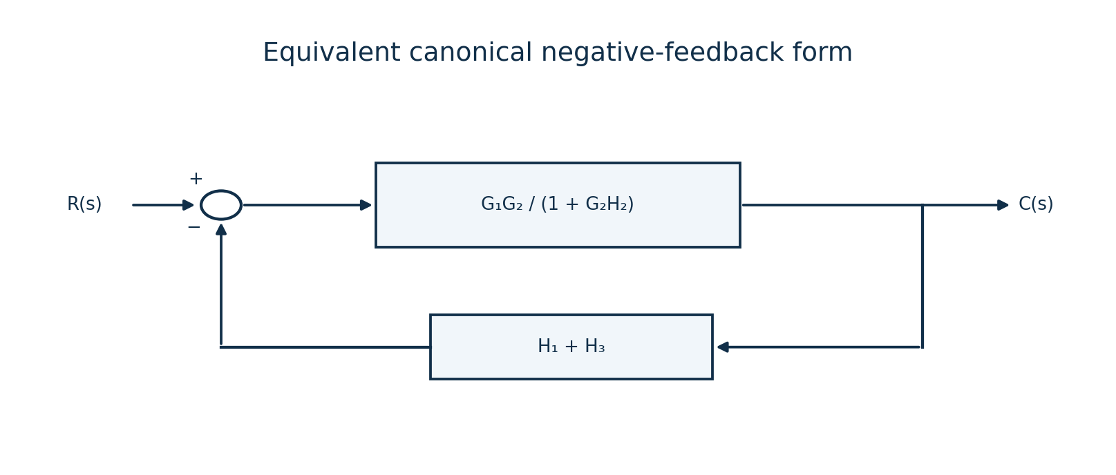
| (i) Canonical form | Forward block Geq = G₁G₂/(1+G₂H₂); feedback block Heq = H₁+H₃, with a negative comparator. |
| (ii) Close the remaining loop | C/R = Geq/(1+GeqHeq) = G₁G₂/[1+G₂H₂+G₁G₂(H₁+H₃)]. |
| Direct equation check | C = G₂{G₁[R−(H₁+H₃)C]−H₂C}, which gives the same denominator. |
Question 2(a)
Write Mason’s gain formula with respect to signal flow graph.
(2 marks)
Answer
The overall gain is M = Σk(PkΔk)/Δ. Pk is the gain of the kth forward path. Δ = 1−ΣLᵢ+Σ(LᵢLⱼ)−Σ(LᵢLⱼLₖ)+…, where products contain only mutually non-touching loops. Δk is obtained by deleting every loop that touches the kth forward path and forming the determinant of the remaining loops.
Question 2(b)
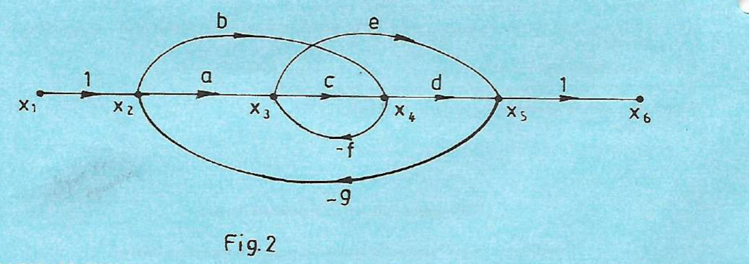
Figure 2 shows a signal flow graph of a control system. Determine the system gain.
(8 marks)
Answer
The gain requested is x₆/x₁. The first and last branches have unit gain. A forward path must follow branch directions without repeating a node; it may move leftward on the page. This creates a fourth forward path through −f.
| Forward path | Gain |
|---|---|
| x₁→x₂→x₃→x₄→x₅→x₆ | P₁ = acd |
| x₁→x₂→x₄→x₅→x₆ | P₂ = bd |
| x₁→x₂→x₃→x₅→x₆ | P₃ = ae |
| x₁→x₂→x₄→x₃→x₅→x₆ | P₄ = −bef |
| Loop | Gain |
|---|---|
| x₃→x₄→x₃ | L₁ = −cf |
| x₂→x₃→x₄→x₅→x₂ | L₂ = −acdg |
| x₂→x₄→x₅→x₂ | L₃ = −bdg |
| x₂→x₃→x₅→x₂ | L₄ = −aeg |
| x₂→x₄→x₃→x₅→x₂ | L₅ = +befg |
| Step | Working |
|---|---|
| Touching-loop check | Every pair of loops shares at least one node. There are no products of non-touching loops. Every loop touches every listed forward path, so all Δk = 1. |
| Graph determinant | Δ = 1−(−cf−acdg−bdg−aeg+befg) = 1+cf+acdg+bdg+aeg−befg. |
| Mason’s formula | M = (acd+bd+ae−bef)/(1+cf+acdg+bdg+aeg−befg). |
| Compact equivalent | Let N = acd+bd+ae−bef. Then x₆/x₁ = N/(1+cf+gN). |
| Independent node check | x₂ = x₁−gx₅; x₃ = ax₂−fx₄; x₄ = bx₂+cx₃; x₅ = dx₄+ex₃; x₆ = x₅. Eliminating x₃ and x₄ gives x₅/x₂ = N/(1+cf), confirming the result. |
Question 2(c)
Explain ‘system modelling’ in control systems.
(2 marks)
Answer
System modelling means representing the relevant physical behaviour of a system mathematically, for example by differential equations, transfer functions or state equations. The model relates inputs, outputs, disturbances and stored-energy variables under stated assumptions, allowing its response and controller performance to be predicted.
Question 2(d)
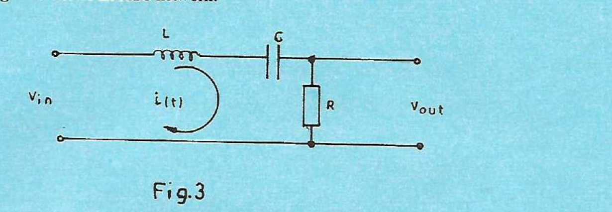
Figure 3 shows an RLC network. Determine the: (i) transfer function Vₒ(s)/Vin(c); (ii) feedback I(s)/Vin(c).
(8 marks)
Answer
The printed denominators use “Vin(c)”; interpret them as the input transform Vin(s). The second requested ratio is an input-current transfer admittance, not a feedback factor. The shown current passes through series L, C and R, with the unloaded output measured across R. Assume zero initial inductor current and capacitor voltage.
| Step | Working |
|---|---|
| Kirchhoff voltage law | vin(t) = L di/dt + (1/C)∫i(t)dt + Ri(t), and vo(t) = Ri(t). |
| Laplace equation | Vin(s) = [sL+1/(sC)+R]I(s). |
| (i) Voltage transfer function | Vₒ/Vin = R/[sL+1/(sC)+R] = RCs/(LCs²+RCs+1). |
| (ii) Current/input-voltage ratio | I/Vin = 1/[sL+1/(sC)+R] = Cs/(LCs²+RCs+1), with units siemens (A/V). |
| Check | Vₒ/Vin = R(I/Vin). At d.c. the capacitor blocks current; at very high frequency the inductor limits current, consistent with the band-pass voltage response. |
Question 3(a)
Define the following terms as used in process control: (i) Control lag; (ii) Process load; (iii) Dead time.
(3 marks)
Answer
| Term | Meaning |
|---|---|
| Control lag | A delay or gradual response in the control system between a change and its correcting effect, caused by controller, actuator, sensor or process dynamics. |
| Process load | The demand or operating burden the process must meet, such as liquid withdrawal rate from a controlled-level tank. |
| Dead time | The time interval after an input/disturbance change before any resulting change first appears at the measured output. |
Question 3(b)
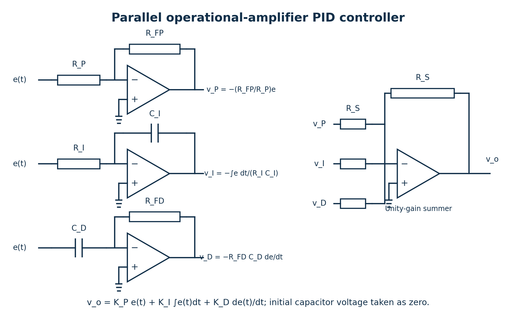
(i) Draw on a OP-Amp based schematic circuit diagram of an analogue PID controller. (ii) Write the expression for the output of the PID controller in b(i).
(5 marks)
Answer
| Step | Working |
|---|---|
| Branch outputs | vP = −(RFP/RP)e; vI = −[1/(RICI)]∫e dt; vD = −RFDCD de/dt, for ideal op-amps and zero initial integrator voltage. |
| Final equal-resistor inverting summer | u = −(vP+vI+vD). Thus u(t) = KPe(t)+KI∫e(t)dt+KD de(t)/dt, where KP = RFP/RP, KI = 1/(RICI), KD = RFDCD. |
| Equivalent controller notation | u(t) = KP[e(t)+(1/TI)∫e(t)dt+TD de(t)/dt], with TI = KP/KI and TD = KD/KP. |
The output sign follows the drawn summing arrangement. Practical derivative circuits limit high-frequency gain, and practical integrators need measures against saturation or windup.
Question 3(c)
Differentiate between electric actuators and solenoid actuators.
(4 marks)
Answer
A solenoid is itself an electrical actuator, so the intended comparison is normally a motor-driven actuator versus a solenoid actuator.
| Motor-driven electrical actuator | Solenoid actuator |
|---|---|
| Produces rotary motion, or linear motion through gearing/screws. | An energised coil attracts a ferromagnetic armature/plunger to produce a short linear stroke, or shifts a valve spool. |
| Can provide controlled speed, position and multi-turn travel. | Commonly gives rapid two-position action over a limited stroke; proportional solenoids are also available. |
Question 3(d)
With the aid of a labelled schematic diagram, describe the operation of a single activating piston actuator controlled by 2-way pressure valve.
(8 marks)
Answer
Interpret “single activating” as single-acting. A complete spring-return circuit must both admit pressure and release the trapped fluid. In standard port/position notation, a two-position 3/2 valve is the usual choice; a literal two-port 2/2 valve by itself cannot provide the required exhaust path. The diagram shows both interpretations explicitly.

- In the normal 3/2 circuit, the piston has one pressure-fed chamber, a rod, seals and a return spring. The rod-side chamber is vented.
- For extension, the valve connects supply P to cylinder port A and blocks exhaust R. Pressure force pA moves the piston against its spring and external load.
- For return, the valve blocks supply and connects A to R. Fluid leaves the working chamber and the spring retracts the piston.
- For the literal 2/2 alternative, opening the supply valve pressurises the cylinder while a separate small bleed permits exhaust. Supply capacity must exceed the bleed flow to extend. Closing the supply lets chamber pressure decay through the bleed so the spring can return the piston. This arrangement consumes fluid while extended; without the added exhaust, a simple 2/2 shutoff traps pressure.
Question 4(a)
(i) Define process variable as used in process control. (ii) Describe each of the following in process control: I. manipulated variable; II. disturbance variable; III. controlled variable.
(4 marks)
Answer
| Variable | Meaning |
|---|---|
| Process variable | A measurable physical quantity describing the process, such as temperature, pressure, flow or level. |
| Manipulated variable | The input deliberately adjusted by the controller to influence the process, such as inlet flow. |
| Disturbance variable | An external or unwanted change that affects the process output independently of the intended control action, such as outlet demand. |
| Controlled variable | The selected process output to be kept at the desired value or trajectory, such as tank level. |
Question 4(b)
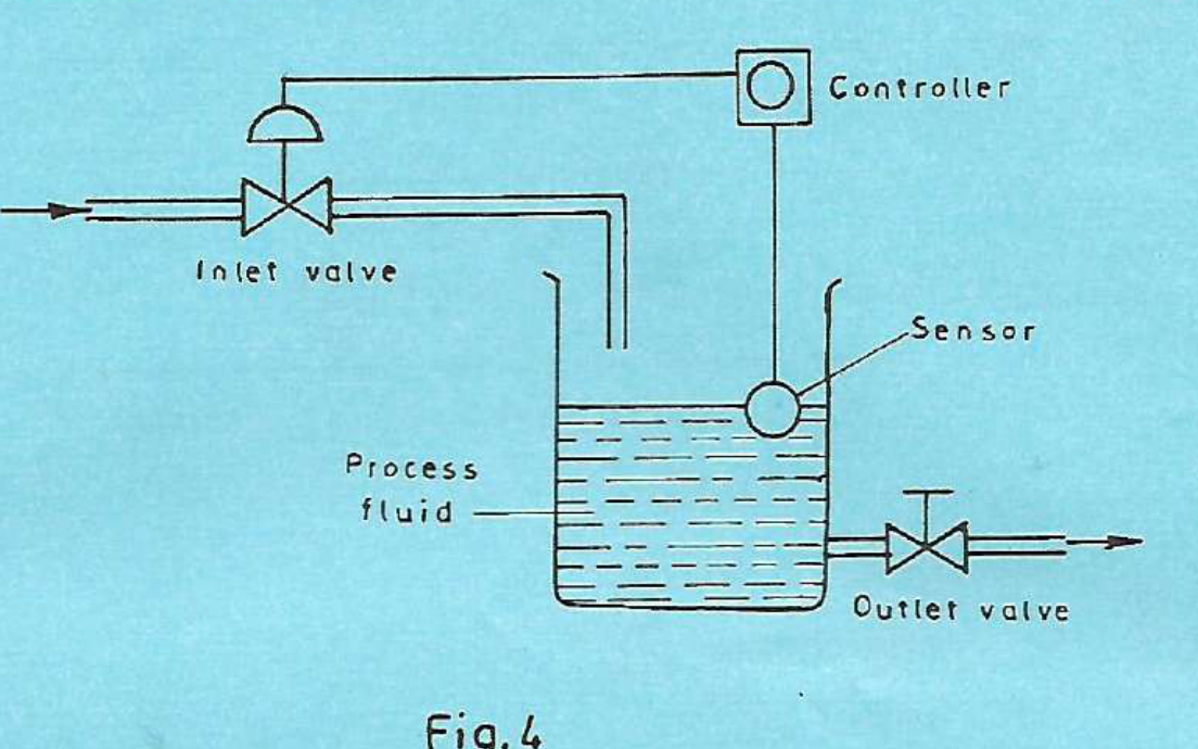
Figure 4 shows a process control. Draw a labelled block diagram representation of the process control.
(5 marks)
Answer
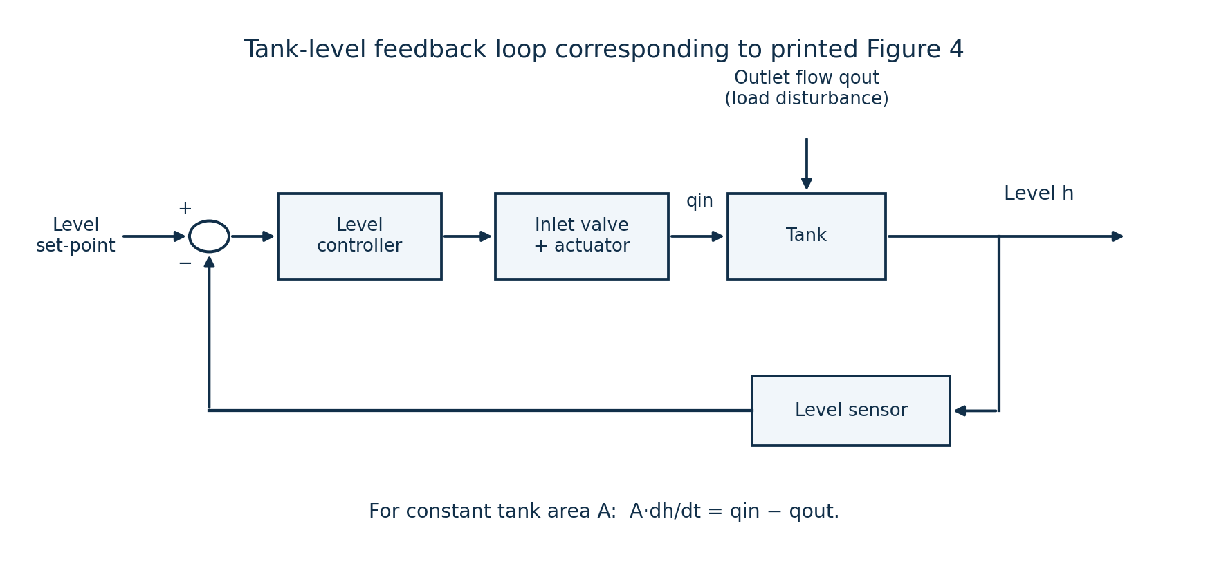
The level sensor returns a signal proportional to actual level. The controller compares it with the desired level and adjusts the inlet valve. A low measured level normally calls for more inflow; a high measured level calls for less. The outlet valve changes withdrawal demand. With constant tank area A, A dh/dt = qin−qout.
Question 4(c)
(i) State two programmable logic controller (PLC) programming languages. (ii) Differentiate between digital and analogue PLC input modules citing one example of input device in each case.
(6 marks)
Answer
(i) Ladder diagram (LD) and function block diagram (FBD).
| Module | Signal handled | Example |
|---|---|---|
| Digital/discrete input | Detects a finite state, usually ON/OFF, with suitable voltage/current thresholds and isolation. | Limit switch or start push-button. |
| Analogue input | Measures a continuously varying quantity over its rated range and converts it to a numerical value, usually with an ADC. | A 4–20 mA pressure transmitter feeding a compatible current-input module. |
Question 4(d)
A stepper motor with 200 steps per revolution makes 160 steps clockwise and 440 steps counter clockwise from a reference point. Determine the: (i) step angle; (ii) final shaft angle.
(5 marks)
Answer
| Step | Working |
|---|---|
| (i) Step angle | α = 360°/200 = 1.8° per step. |
| Signed step count | Choose clockwise positive. Net steps = 160−440 = −280. |
| (ii) Signed cumulative angle | θ = −280(1.8°) = −504°, meaning 504° counter-clockwise from the reference. |
| Equivalent orientation within one revolution | 504° counter-clockwise = one full turn plus 144° counter-clockwise. The same final orientation is 216° clockwise. Cumulative travel angle and modulo-360° orientation are different quantities. |
Question 5(a)
(i) State three advantages of thermistors over platinum resistance thermometer. (ii) Explain the principle of operation of resistance temperature sensor.
(7 marks)
Answer
- (i) Thermistors usually have a larger fractional resistance change per degree over their intended range, giving high sensitivity.
- They can be made very small, giving low thermal mass and a fast response when mounted comparably.
- They are often less expensive than precision platinum resistance elements for a limited measurement range.
These are typical design comparisons, not universal claims. Platinum RTDs generally offer a wider useful range and better long-term linearity/stability; thermistors are strongly nonlinear.
(ii) A resistance temperature sensor uses a repeatable dependence of resistance on temperature. Pass a small known measuring current through the element or use a bridge; infer resistance from the voltage and convert it to temperature using calibration. For a metal RTD over a limited range, R(T) ≈ R₀[1+α(T−T₀)]. Platinum has a positive temperature coefficient; common NTC thermistors decrease in resistance as temperature rises. Limit the excitation to avoid self-heating.
Question 5(b)
A quartz piezo-electric transducer has thickness of 2.1 mm, voltage sensitivity of 0.054 Vm/N and a permittivity of 36 × 10⁻¹² F/m. If the transducer is subjected to a pressure of 60 kN/m², determine the: (i) output voltage generated; (ii) charge sensitivity.
(5 marks)
Answer
Let g = 0.054 V·m/N be the piezoelectric voltage coefficient, ε = 36×10⁻¹² F/m the absolute permittivity, t the thickness and p the applied stress/pressure. Assume the relevant sensing mode and a high-impedance output measurement.
| Step | Working |
|---|---|
| Convert data | t = 2.1×10⁻³ m; p = 60,000 N/m². |
| (i) Generated voltage | Electric field E = gp, hence V = Et = gpt = 0.054(60,000)(2.1×10⁻³) = 6.804 V in magnitude. |
| (ii) Charge sensitivity | The charge coefficient d = εg = (36×10⁻¹²)(0.054) = 1.944×10⁻¹² C/N = 1.944 pC/N. |
| Units and polarity | (F/m)(V·m/N) = C/N. Voltage polarity depends on electrode and crystal orientation. Total charge Q = dF cannot be calculated without the loaded area or force. |
Question 5(c)
Differentiate between absolute pressure and gauge pressure with reference to pressure measurements.
(2 marks)
Answer
Absolute pressure is measured relative to a perfect vacuum. Gauge pressure is measured relative to the local atmospheric pressure. Thus pabs = pgauge + patmospheric; a gauge pressure below atmospheric is negative, while ordinary absolute pressure remains non-negative.
Question 5(d)
With the aid of a labelled diagram, describe measurement of viscosity of fluid using pressure drop method.
(6 marks)
Answer
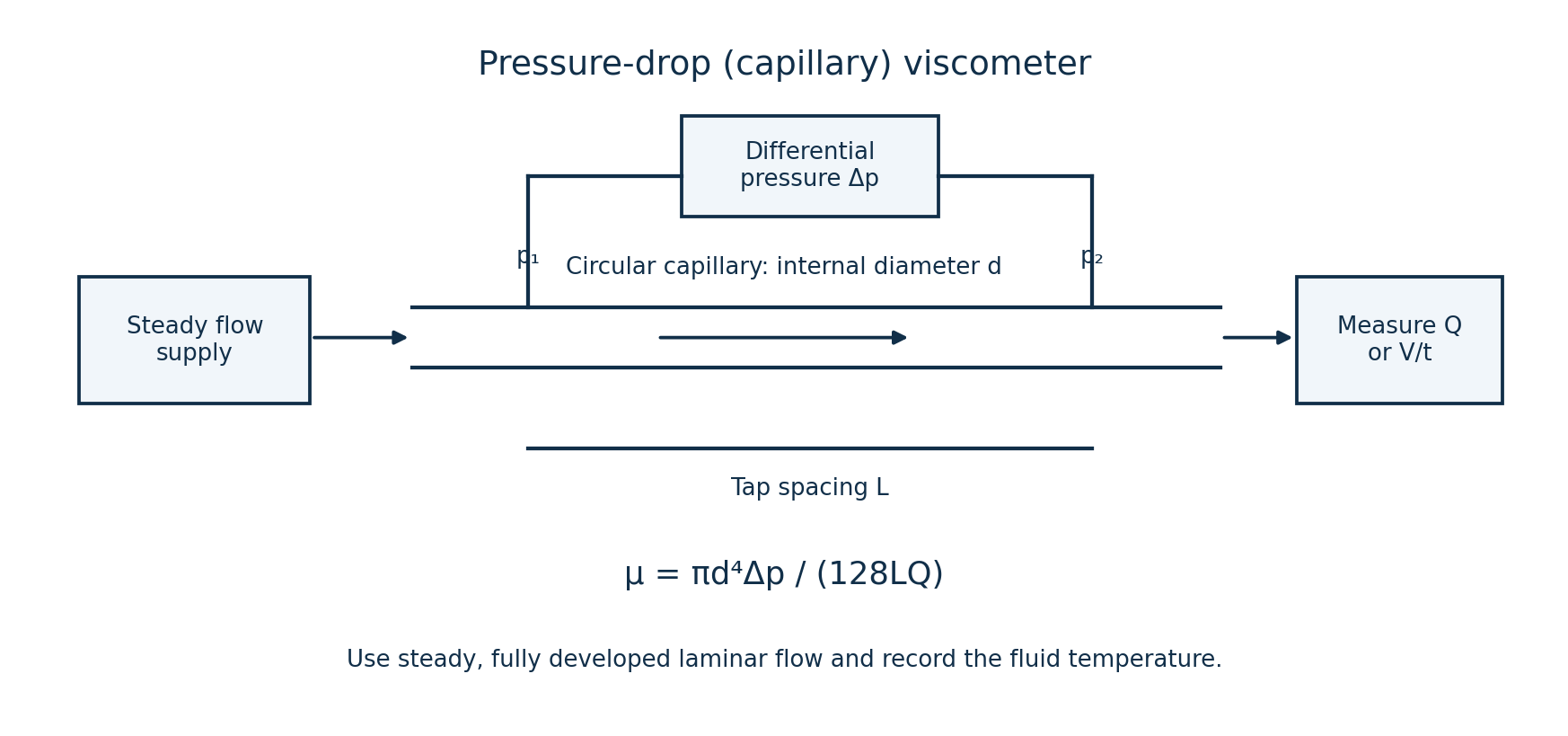
- Pass the fluid steadily through a known circular capillary diameter d. Measure pressure difference Δp between taps separated by a known length L.
- Measure the volume flow rate Q, for example by collecting volume V over time t, and record/control the sample temperature.
- For fully developed laminar Newtonian flow, Δp = 128μLQ/(πd⁴), so dynamic viscosity μ = πd⁴Δp/(128LQ).
- Use pressure taps beyond the entrance-development region and account for any relevant minor losses. Check that the flow is laminar and that the sample behaves as Newtonian over the test range; otherwise this equation does not give a unique material viscosity.
Question 6(a)
State two types of strain gauges.
(2 marks)
Answer
- Bonded metallic resistance strain gauge, such as a wire or foil gauge.
- Semiconductor piezoresistive strain gauge.
Question 6(b)
Figure 5 shows a strain gauge connected to a wheatstone bridge circuit. (i) Describe the operation of the circuit. (ii) A strain of 0.0025 m causes the resistance of the strain gauge to change by 100 Ω. Determine the: I. output voltage, Vout; II. gauge factor.
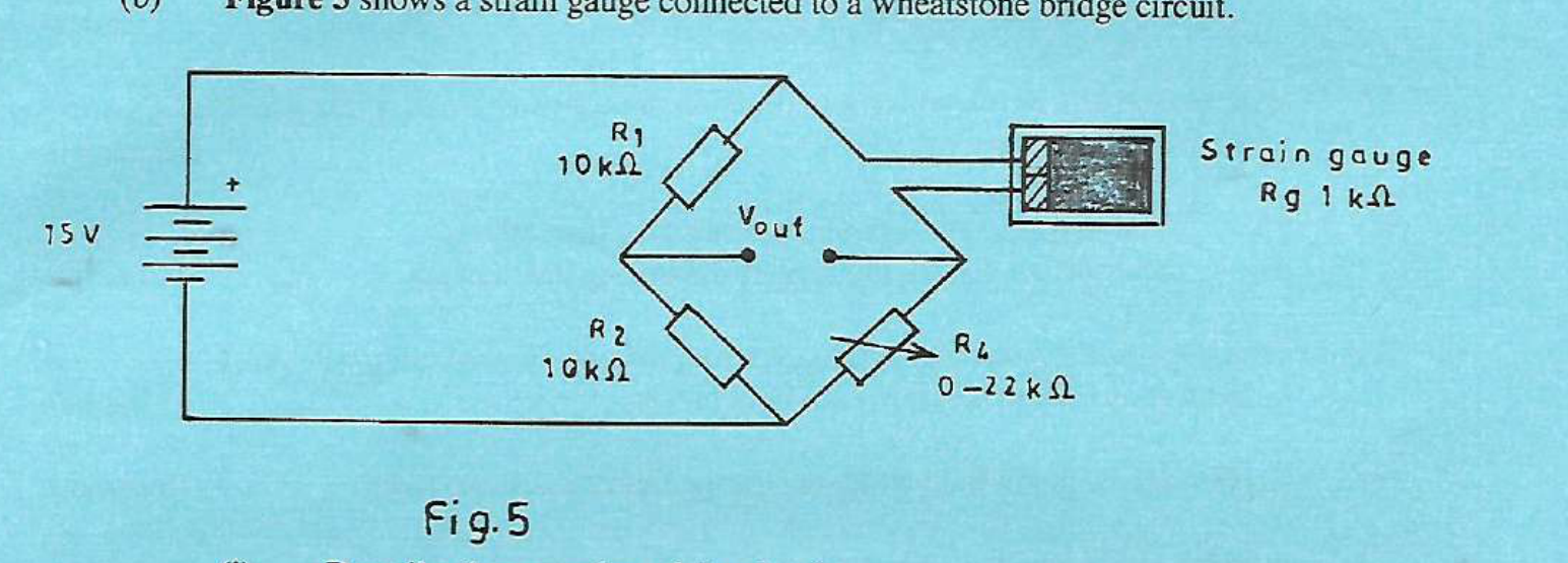
(9 marks)
Answer
(i) The 15 V source excites two voltage dividers. R₁ = R₂ = 10 kΩ form the left leg; the 1 kΩ gauge Rg and adjustable R₄ form the right leg. Adjust R₄ to balance the unloaded bridge. Strain changes Rg, unbalancing the divider voltages and producing a differential output.
For a numerical result, assume the bridge was initially balanced at R₄ = 1 kΩ, R₄ remains fixed during measurement, the gauge resistance increases by 100 Ω, and the output meter does not load the bridge. Define Vout = Vleft−Vright. The printed “strain of 0.0025 m” is dimensionally inconsistent; first interpret 0.0025 as dimensionless strain.
| Step | Working |
|---|---|
| Initial balance | Vleft = 15R₂/(R₁+R₂) = 7.5 V. Balance requires R₄/(Rg+R₄) = 1/2, so R₄ = Rg = 1000 Ω. |
| Loaded right-divider voltage | Rg,new = 1000+100 = 1100 Ω. Vright = 15(1000)/(1100+1000) = 7.142857 V. |
| I. Exact output voltage | Vout = 7.5−7.142857 = +0.357143 V for the defined polarity. Reversing the meter leads reverses the sign. |
| II. Gauge factor | GF = (ΔR/Rg)/ε = (100/1000)/0.0025 = 40, dimensionless. |
| If “change” is a decrease | For Rg,new = 900 Ω, Vout = 7.5−15(1000)/(900+1000) = −0.394737 V; the signed gauge factor also depends on the strain sign. |
| If 0.0025 m means extension instead | Strain would be ε = ΔL/L₀ = 0.0025/L₀. The original gauge length L₀ is then needed; GF = 40L₀ when L₀ is in metres. A unique gauge factor is unavailable under that interpretation. |
Use the exact divider result because ΔR/R = 0.1 is not very small; the usual linear quarter-bridge approximation is less accurate here.
Question 6(c)
Define ‘inductive proximity sensor’.
(1 marks)
Answer
An inductive proximity sensor detects a nearby metal target without physical contact by sensing the target’s effect on an alternating magnetic field produced by a coil.
Question 6(d)
Figure 6 shows a schematic circuit diagram of an inductive proximity sensor. (i) Describe its operation. (ii) Sketch the output waveforms when the metal object is present and when absent.
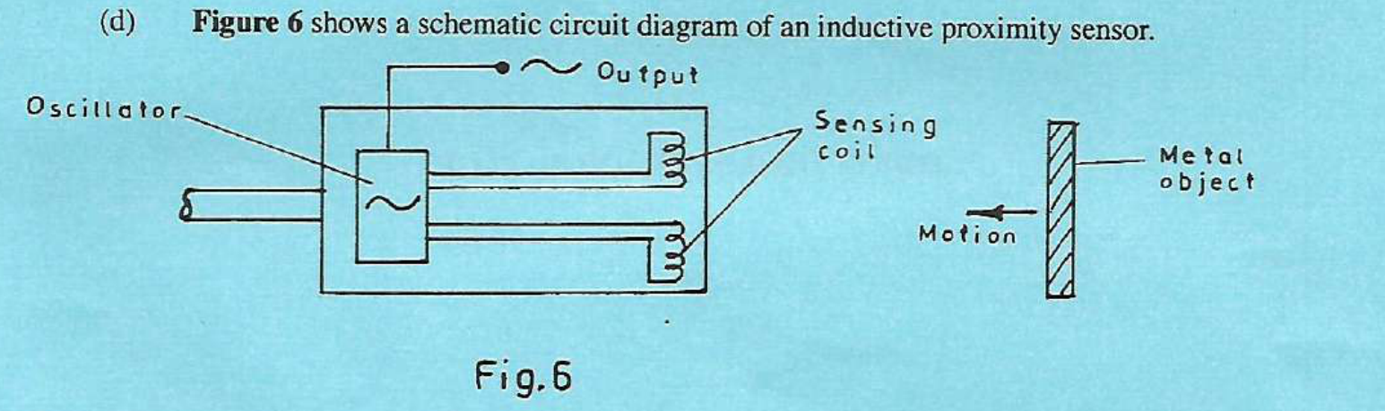
(8 marks)
Answer
- (i) An oscillator drives the sensing coil to produce an alternating magnetic field at the sensor face.
- A nearby conducting metal target develops eddy currents. These draw energy from the field and reduce the oscillator amplitude, potentially stopping oscillation.
- An amplitude detector and switching stage can convert the oscillator change to a discrete target-present signal. Different normally-open/normally-closed or PNP/NPN outputs have different switching polarities.
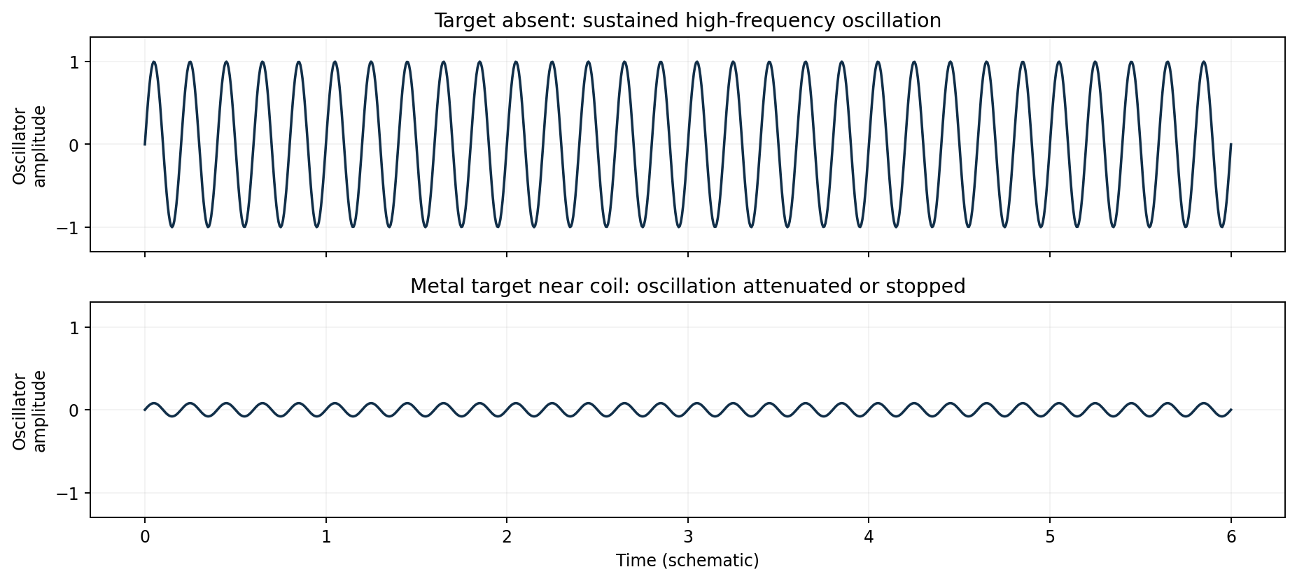
(ii) The printed output tap is at the oscillator, so the sketches show its high-frequency analogue waveform. A complete switching sensor would instead give a two-state output after detection; its polarity is not specified in this question.
Question 7(a)
(i) State three areas of application of humidity transducers. (ii) Differentiate between capacitive and resistive type humidity sensors.
(7 marks)
Answer
- (i) Heating, ventilation and air-conditioning control.
- Drying processes or food/pharmaceutical storage monitoring.
- Greenhouse or environmental/weather monitoring.
| Sensor | Sensing principle |
|---|---|
| Capacitive humidity sensor | Moisture absorbed in a dielectric changes its permittivity, changing the capacitance between electrodes. The electronics relate this change to humidity after calibration. |
| Resistive humidity sensor | Moisture changes the conductivity/resistance of a hygroscopic sensing film between electrodes. The measured resistance is related to humidity by calibration. |
Both types commonly measure relative humidity and require temperature compensation and suitable contamination protection.
Question 7(b)
Outline two maintenance procedures carried out on turbine flowmeter.
(2 marks)
Answer
- Inspect and clean the rotor, flow path and any fitted upstream strainer using a method compatible with the meter and fluid; remove deposits that restrict the rotor.
- Inspect rotor bearings and pickup condition, verify free movement/signal integrity, and check calibration or the K-factor against a reference; replace worn parts as specified by the manufacturer.
Question 7(c)
The manometer pressure difference in a venturi meter is 18 cm for a fluid of density 0.84 g/cm³. The force of gravity is 9.8 m/s². Determine the meter reading.
(3 marks)
Answer
Interpret the reading as a pressure difference corresponding to a head of 18 cm of the stated fluid, because no Venturi diameters or discharge coefficient are given.
| Step | Working |
|---|---|
| Convert units | ρ = 0.84 g/cm³ = 840 kg/m³; h = 18 cm = 0.18 m. |
| Pressure difference | Δp = ρgh = 840(9.8)(0.18) = 1481.76 Pa. |
| Answer | Meter pressure difference ≈ 1.482 kPa. |
If the 18 cm is a differential U-tube level difference between a separate manometer liquid and the flowing fluid, their density difference must be used: Δp = (ρm−ρf)gh for equal-elevation taps. Both densities are then needed. A volume flow rate cannot be obtained from the stated data alone.
Question 7(d)
With the aid of a labelled diagram, describe the construction of linear variable Differential Transformer (LVDT).
(8 marks)
Answer
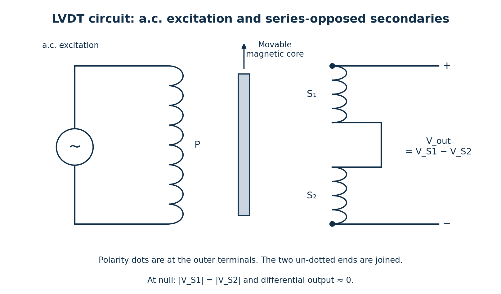
- The primary winding P lies centrally on an insulated cylindrical former and is supplied with a suitable a.c. excitation.
- Two identical secondary windings S₁ and S₂ are arranged symmetrically on either side of the primary and connected in series opposition.
- A movable high-permeability magnetic core slides axially within the hollow former without electrical contact with the windings. A non-magnetic rod connects it to the moving object.
- A protective housing and magnetic shielding limit external-field interference; suitable supports maintain alignment.
- At the central null, the induced secondary voltages are equal and oppose, giving approximately zero differential output. Core displacement increases coupling to one secondary and decreases it to the other.
- An a.c. signal conditioner/demodulator reads the difference Vₒ = VS₁−VS₂. Within the calibrated range its magnitude represents displacement and its phase relative to excitation identifies direction.
Question 8(a)
(i) State two sources of errors in measuring instruments. (ii) Describe the controlling type of measuring instruments.
(4 marks)
Answer
- (i) Instrumental error, such as calibration drift, zero offset, friction or wear.
- Environmental error, such as ambient-temperature change, vibration or electromagnetic interference.
(ii) A controlling instrument measures a process quantity, compares it with a specified value or limit, and produces an action that regulates the process. For example, a thermostat switches a heater to maintain temperature, while a level controller adjusts a valve. Its function includes control action in addition to measurement or indication.
Question 8(b)
With the aid of a labelled diagram, describe the operation of ultrasonic level transducer as used to measure tank liquid level.
(7 marks)
Answer

- Mount the transducer at a known height H above the tank datum. It emits a short ultrasonic pulse towards the liquid surface.
- The surface reflects an echo to the receiver. Electronic timing measures the round-trip travel time t between transmission and echo detection.
- If sound speed in the vapour space is c, the distance from sensor to surface is d = ct/2; the division by two accounts for the outward and return paths.
- Calculate liquid height h = H−d = H−ct/2 and convert it to a display or control signal.
- Compensate for temperature/composition effects on sound speed and observe the sensor’s blanking distance; foam, turbulence or obstructions can produce weak or false echoes.
Question 8(c)
Explain viscousity in fluid citing two properties of a viscous fluid.
(3 marks)
Answer
Viscosity is the resistance of a fluid to relative shearing motion between adjacent layers. For a Newtonian fluid, τ = μ du/dy, where μ is dynamic viscosity.
- A viscous fluid develops shear stress when neighbouring layers move at different velocities; larger μ means more stress for the same velocity gradient.
- Viscous flow dissipates mechanical energy as internal energy, producing pressure/head loss in a pipe.
These properties do not imply that every viscous fluid is Newtonian or that viscosity is independent of temperature.
Question 8(d)
With the aid of labelled circuit diagrams, differentiate between photoconductive and photo voltaic modes of a photo diode.
(6 marks)
Answer
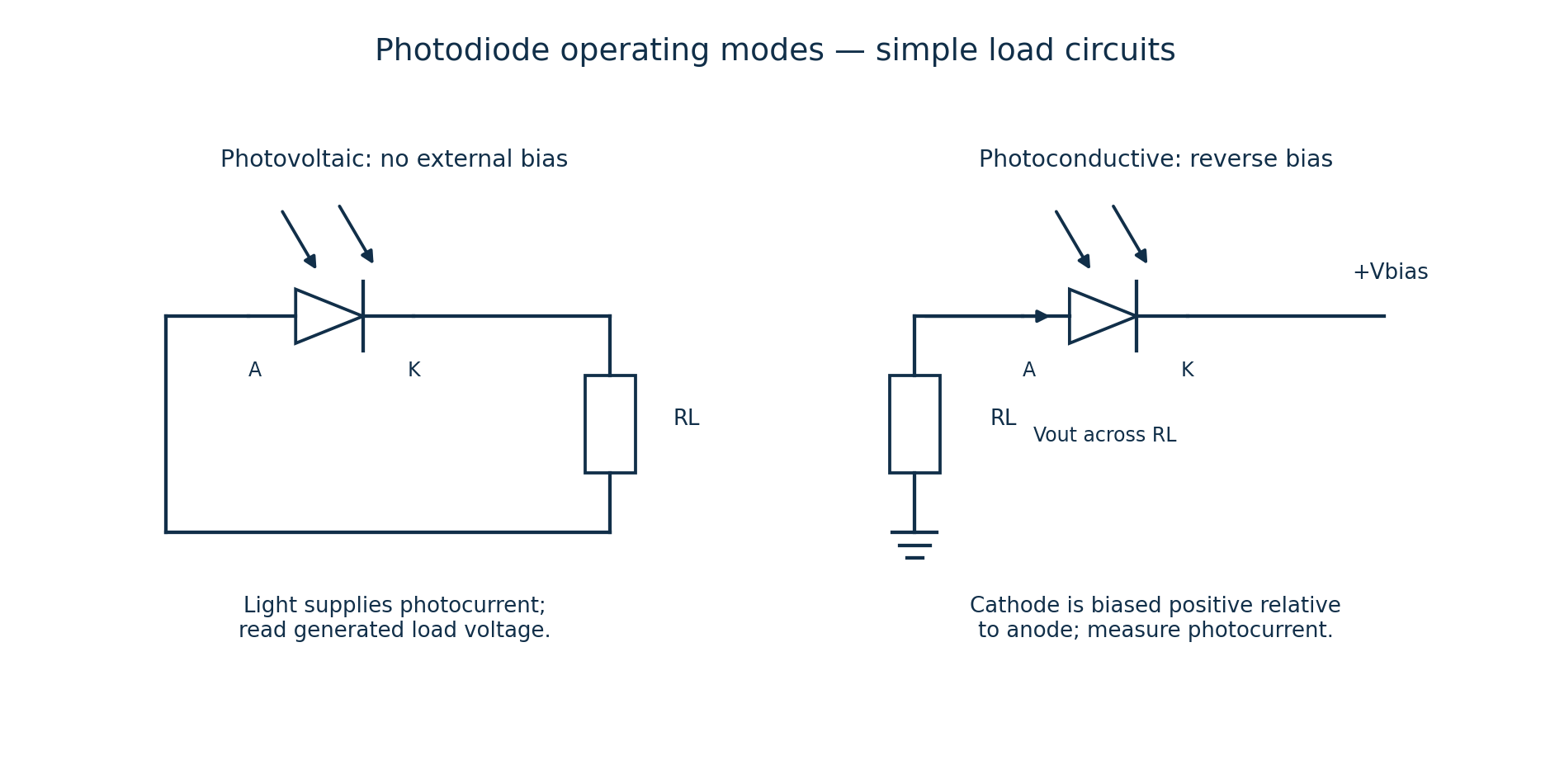
| Feature | Photoconductive mode | Photovoltaic mode |
|---|---|---|
| Bias connection | Apply reverse bias: cathode more positive than anode. | Use no external bias source across the detector. |
| Signal | Light-generated carriers produce a reverse photocurrent, converted to voltage by a resistor or amplifier. | The illuminated junction supplies current/voltage to a load; a zero-bias amplifier may also measure its short-circuit photocurrent. |
| Typical trade-off | Reverse bias reduces junction capacitance and improves speed, but increases dark current and associated noise. | Usually lower dark-current noise; commonly chosen for low-light/precision work at lower bandwidth. |
“No external bias” does not mean that an illuminated loaded photodiode produces zero output voltage. The output polarity follows the electrode connections shown.