Plant Control Systems and Automation — October/November 2022
KNEC Diploma in Mechanical Engineering — Module III. Paper code: 2502/302.
Questions are transcribed from the supplied examination paper. The independent revision answers are not official KNEC marking schemes. All 8 questions, including optional questions, are answered.
The supplied scan begins at printed page 2 and contains Questions 1–8 followed by 8051 reference appendices. Cover instructions are absent. All eight questions and their subparts are answered for revision.
Question 2(c) calls the drawn RLC circuit an “RC network”; the answer follows all components shown. The motor lamp follows the commanded run state because no rotation-feedback sensor is specified. Robot resolution/accuracy conventions and cumulative versus modulo stepper angles are made explicit.
Question 1(a)
State three classifications of control systems.
(3 marks)
Answer
- By feedback: open-loop and closed-loop systems.
- By linearity: linear and nonlinear systems.
- By signal/time representation: continuous-time and discrete-time systems; a hybrid system combines continuous and discrete behaviour.
Question 1(b)
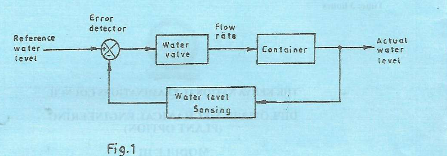
Figure 1 shows a block diagram of water level control system. (i) Identify the type of control system. (ii) Describe each component of the control system.
(7 marks)
Answer
(i) It is a closed-loop, negative-feedback water-level control system: measured actual level is returned to the error detector.
| Component/signal | Function |
|---|---|
| Reference water level | The desired level or set-point. |
| Error detector | Compares desired level with the sensed actual level and generates their difference. |
| Water valve | Final control element: varies the inlet flow rate in response to the correcting command. |
| Container | The process being controlled; its water level changes according to the net inflow minus outflow. |
| Actual water level | The controlled output. |
| Water-level sensing and feedback | Measures the output and returns a corresponding signal to the error detector. |
If level falls below its set-point, the control action increases inflow; if it rises above the set-point, inflow is reduced, assuming the usual valve/controller action.
Question 1(c)
Explain each of the following terms as used in control systems: (i) disturbances; (ii) control action.
(4 marks)
Answer
| Term | Meaning and example |
|---|---|
| Disturbances | Unwanted inputs or changes that affect the controlled output, such as changing outlet demand in a level-control tank. |
| Control action | The controller’s deliberate response used to influence the process and reduce error, such as increasing the inlet-valve opening when the level is below its set-point. |
Question 1(d)
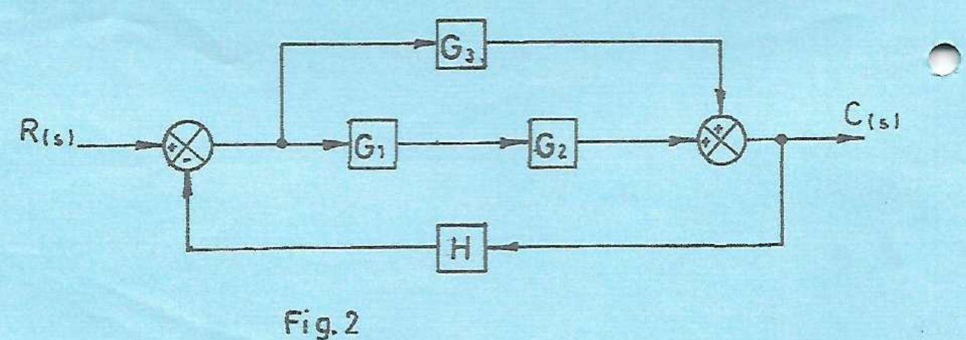
Figure 2 shows a block diagram of a control system. (i) Reduce the block diagram to its equivalent canonical form. (ii) Determine the expression for the transfer function.
(6 marks)
Answer
Both forward branches enter the output summer positively. The output is fed back negatively through H.
| Step | Working |
|---|---|
| Series branch | The gain of the lower forward branch is G₁G₂. |
| Parallel combination | The upper branch G₃ and lower branch G₁G₂ have the same input and their outputs add: Geq = G₁G₂+G₃. |
| (i) Canonical form | Use forward block Geq = G₁G₂+G₃ and negative feedback block H. |
| (ii) Transfer function | Let E = R−HC and C = GeqE. Therefore C/R = (G₁G₂+G₃)/[1+H(G₁G₂+G₃)]. |

Question 2(a)
State the electrical equivalent of each of the following physical variables: (i) torque; (ii) moment of inertia; (iii) damping coefficient.
(3 marks)
Answer
State the analogy used. In the torque–voltage (impedance) analogy, angular velocity corresponds to current: T = J dω/dt+Bω+K∫ωdt corresponds to V = L di/dt+Ri+(1/C)∫i dt.
| Mechanical quantity | Electrical equivalent in torque–voltage analogy |
|---|---|
| Torque T | Voltage V. |
| Moment of inertia J | Inductance L. |
| Viscous damping coefficient B | Resistance R. |
An alternative torque–current (mobility) analogy gives torque↔current, inertia↔capacitance and damping↔conductance (1/R). Do not mix entries from the two analogies.
Question 2(b)
Explain the need for ‘system modelling’ in control systems.
(2 marks)
Answer
A model provides a mathematical relationship between system inputs and outputs, enabling prediction of transient/steady-state response and stability. It allows controller design, simulation and comparison of changes before building or altering the physical plant. The assumptions and operating range determine how reliably those predictions apply.
Question 2(c)
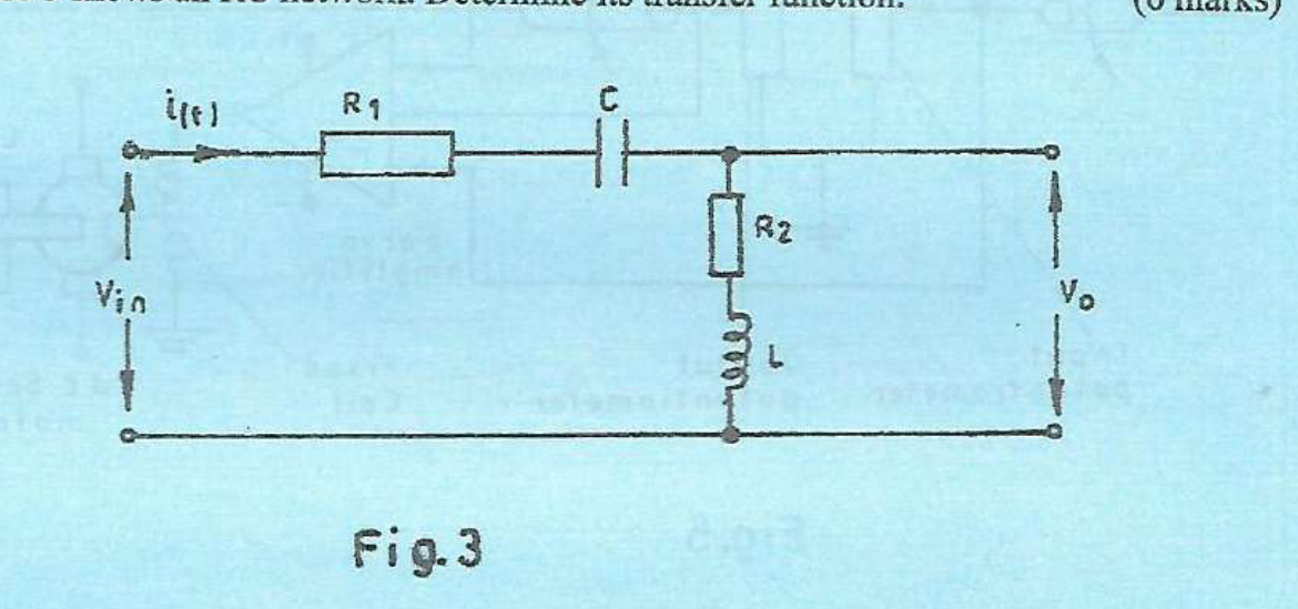
Figure 3 shows an RC network. Determine its transfer function.
(6 marks)
Answer
Although the question says “RC”, the drawing includes an inductor L in series with the output resistor R₂. Follow the circuit as drawn. Assume an unloaded output, ideal components and zero initial stored energy.
| Step | Working |
|---|---|
| Series impedances | The same current flows through R₁, C, R₂ and L. Zin = R₁+1/(sC)+R₂+sL. |
| Output impedance | Vₒ is measured across the entire R₂–L branch: Zout = R₂+sL. |
| Voltage divider | Vₒ/Vin = (R₂+sL)/[R₁+R₂+sL+1/(sC)]. |
| Polynomial form | Multiply numerator and denominator by sC: Vₒ(s)/Vin(s) = (LCs²+R₂Cs)/[LCs²+(R₁+R₂)Cs+1]. |
| Limit checks | At d.c., the series capacitor blocks current, so Vₒ/Vin→0. At very high frequency, the inductor dominates the series impedance and the output ratio approaches 1. |
Question 2(d)
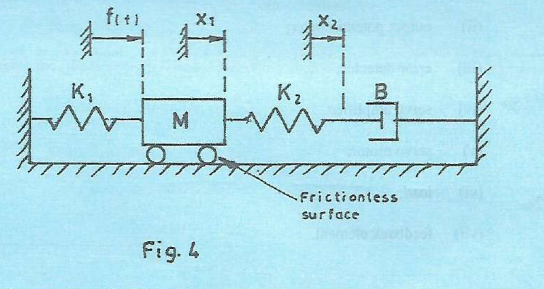
Figure 4 shows a mechanical system. (i) Obtain the differential equations describing the system. (ii) Determine the transfer function X₁(s)/F(s).
(9 marks)
Answer
Use positive displacement to the right. M is the moving mass at x₁, K₁ connects the mass to the left fixed wall, K₂ connects the mass to a massless junction x₂, and viscous damper B connects that junction to the right fixed wall. The supporting surface is frictionless.
| Step | Working |
|---|---|
| (i) Mass force balance | M d²x₁/dt² = f(t)−K₁x₁−K₂(x₁−x₂), or Mẍ₁+(K₁+K₂)x₁−K₂x₂ = f(t). |
| Massless-junction force balance | K₂(x₁−x₂) = B dx₂/dt, or Bẋ₂+K₂x₂ = K₂x₁. |
| Zero-initial-condition transforms | [Ms²+K₁+K₂]X₁−K₂X₂ = F; [Bs+K₂]X₂ = K₂X₁. |
| Eliminate X₂ | X₂ = K₂X₁/(Bs+K₂). Hence {[Ms²+K₁+K₂]−K₂²/(Bs+K₂)}X₁ = F. |
| (ii) Transfer function | X₁/F = (Bs+K₂)/{[Ms²+K₁+K₂](Bs+K₂)−K₂²}. |
| Expanded denominator | X₁(s)/F(s) = (Bs+K₂)/[MBs³+MK₂s²+B(K₁+K₂)s+K₁K₂]. |
| Static check | At s=0, X₁/F = 1/K₁: the series damper relaxes in a static condition, leaving K₁ to support the applied load. |
Question 3(a)
(i) Define ‘servo-mechanism’. (ii) State three features of a servo-mechanism.
(4 marks)
Answer
(i) A servomechanism is an automatic feedback system used to make mechanical position, speed or motion follow a commanded value.
- (ii) It measures the actual motion and compares it with a reference, producing an error signal.
- It uses an amplifier and powered actuator to drive the load in the direction that reduces the error.
- It is designed for accurate tracking and appropriate dynamic response, with feedback helping reject load disturbances.
Question 3(b)
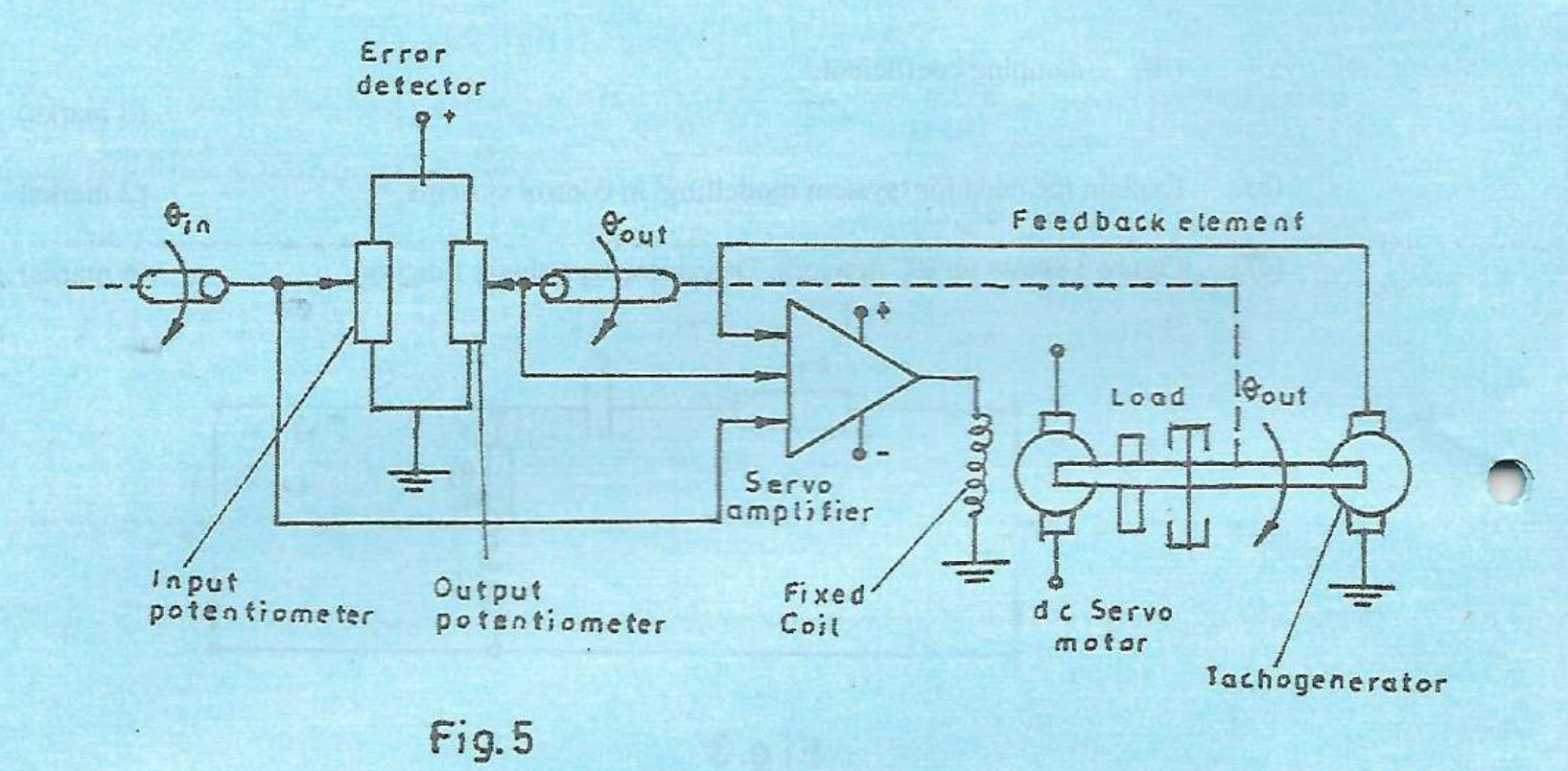
Figure 5 shows a schematic circuit diagram of a remote position control system. State the function of each of the following elements: (i) input potentiometer; (ii) output potentiometer; (iii) error detector; (iv) servo amplifier; (v) servo motor; (vi) load; (vii) feedback element.
(7 marks)
Answer
| Element | Function |
|---|---|
| (i) Input potentiometer | Converts the demanded shaft angle θin into a reference voltage. |
| (ii) Output potentiometer | Converts actual load/shaft angle θout into a position-feedback voltage. |
| (iii) Error detector | Compares the reference and feedback signals and produces a signed position-error signal. |
| (iv) Servo amplifier | Raises the low-power error signal to a level suitable for driving the motor, with the required polarity/control response. |
| (v) Servo motor | Converts electrical power into controlled torque and rotation to reposition the load. |
| (vi) Load | The mechanism whose position is to follow the command; it imposes inertia and resisting torque. |
| (vii) Feedback element | Returns information about actual output motion. The position feedback reduces angle error; the shown tachogenerator supplies speed-proportional feedback that can add damping and reduce overshoot. |
Question 3(c)
(i) State three merits of using stepper motor as an actuator. (ii) A stepper motor of step angle 15° is programmed to rotate 220 steps clockwise and 80 steps counter clockwise from a reference point. Determine the motor final angle from the reference point.
(9 marks)
Answer
- (i) Angular position is commanded by a countable number of input pulses.
- It provides repeatable incremental movement and holding torque at standstill when suitably energised.
- Speed and direction are readily controlled by pulse frequency and phase sequence; an open-loop drive can be used within its torque/acceleration limits.
A stepper can lose position if it misses steps, so open-loop positioning assumes the load and drive are correctly matched.
| Step | Working |
|---|---|
| Choose a sign convention | Take clockwise as positive. Net step count = 220−80 = 140 clockwise steps. |
| Cumulative final angle | θ = 140×15° = 2100° clockwise from the reference. |
| Equivalent orientation | 2100° = 5×360°+300°. The shaft is therefore at 300° clockwise (equivalently 60° counter-clockwise) modulo one revolution, after five full turns plus 300° of net clockwise rotation. |
Question 4(a)
Define each of the following terms as used in process control: (i) process variable; (ii) set point; (iii) process load.
(3 marks)
Answer
| Term | Definition |
|---|---|
| Process variable | A measurable condition of the process, such as pressure, temperature, flow or level. |
| Set point | The required value of the controlled process variable. |
| Process load | The demand or operating burden that the process must satisfy, such as heat withdrawal from a furnace or liquid withdrawal from a tank. |
Question 4(b)
With the aid of a block diagram, describe the components of a process control system.
(8 marks)
Answer
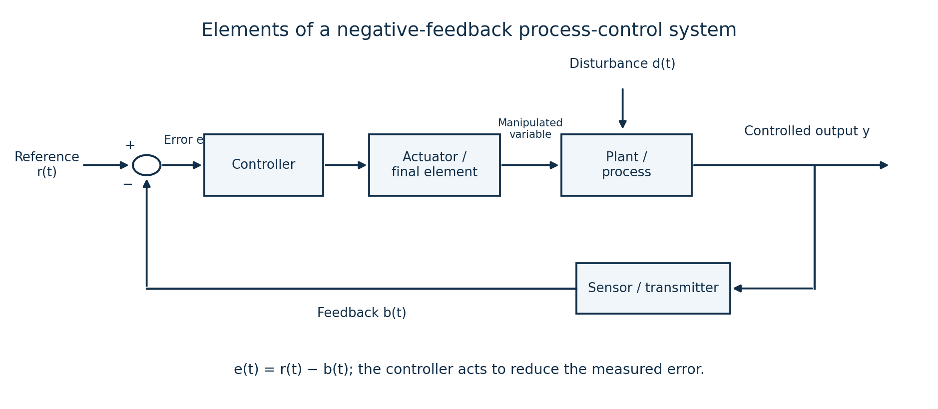
| Component | Description |
|---|---|
| Set-point/reference unit | Provides the desired value in a form compatible with the measurement. |
| Comparator/error detector | Calculates error = desired value−measured value. |
| Controller | Applies its control law to the error and produces a command. |
| Actuator/final control element | Changes the manipulated variable, for example moving a control valve to change flow. |
| Process/plant | The physical equipment or operation that responds to the manipulated input and disturbances. |
| Sensor/transmitter | Measures the controlled output and converts it to a suitable feedback signal. |
| Feedback connection | Returns the measured signal to the comparator to close the loop. |
| Disturbance input | Represents load changes affecting the output; the loop adjusts the manipulated input to counter their effect. |
Question 4(c)
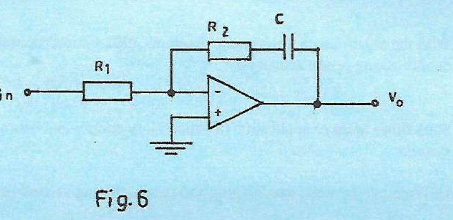
Figure 6 shows a schematic circuit diagram of an analogue controller. (i) State the type of the controller. (ii) Derive the expression for the output voltage, Vₒ.
(6 marks)
Answer
(i) It is an inverting proportional-plus-integral (PI) controller. Its feedback impedance is a series resistor R₂ and capacitor C.
| Step | Working |
|---|---|
| Ideal op-amp conditions | The non-inverting input is grounded; with negative feedback, the inverting node is at virtual ground and draws negligible current. |
| Input and feedback impedances | Zin = R₁; Zf = R₂+1/(sC). |
| Voltage transfer function | Vₒ(s)/Vin(s) = −Zf/Zin = −R₂/R₁−1/(R₁Cs). |
| (ii) Time-domain output | vₒ(t) = −(R₂/R₁)vin(t)−[1/(R₁C)]∫₀ᵗvin(τ)dτ, for zero initial capacitor voltage. |
| Controller constants | The magnitudes are KP = R₂/R₁ and KI = 1/(R₁C), or TI = R₂C. The minus sign is the inversion of the circuit and must be included when assigning overall loop polarity. |
Question 4(d)
State the function of each of the following analogue controllers: (i) proportional controller; (ii) integral controller; (iii) derivative controller.
(3 marks)
Answer
| Controller | Function |
|---|---|
| Proportional | Produces a correction proportional to the present error: uP = KPe. |
| Integral | Accumulates error over time: uI = KI∫e dt. In a suitable stable loop it removes steady offset to a constant reference/disturbance. |
| Derivative | Responds to the rate of change of error: uD = KD de/dt, providing anticipatory/damping action. Practical implementations filter high-frequency noise. |
Question 5(a)
State: (i) two types of fluid based actuators used in control system; (ii) three merits of the actuators in (a)(i).
(5 marks)
Answer
(i) Pneumatic actuators use compressed gas; hydraulic actuators use pressurised liquid.
| Merit | Application/qualification |
|---|---|
| High force or torque for actuator size | Especially a merit of high-pressure hydraulic actuators. |
| Fast and convenient linear movement | Cylinders produce linear strokes directly; pneumatic systems are useful for rapid repetitive strokes. |
| Remote and controllable actuation | Valves and fluid lines allow force, speed and direction to be controlled at a distance; overload force can be limited through appropriate pressure control. |
The advantages differ between hydraulic and pneumatic designs. Neither type should be assumed leak-free, perfectly rigid or loss-free.
Question 5(b)
(i) Draw the symbol of a bidirectional solenoid valve. (ii) With the aid of labelled constructional diagrams, describe the operation of the solenoid valve in (b)(i).
(9 marks)
Answer
Use a double-solenoid 4/2 directional valve as one valid bidirectional example. It has four ports (P supply, T return/exhaust, A and B working ports), two spool positions and a solenoid at each end. The two squares in the symbol show alternative positions of one valve, not two separate valves.

- The valve body contains a precision bore with a sliding spool. Lands on the spool block or open the port passages. End armatures/solenoids shift the spool axially.
- With coil A actuated, the selected spool position connects P→A and B→T. A connected double-acting cylinder moves in one direction.
- With coil B actuated, the spool shifts to connect P→B and A→T, reversing the cylinder motion.
- For a bistable double-solenoid design, the spool normally retains its last position when both coils are off; other designs use different centring/return arrangements. Avoid simultaneous opposing commands.
- The construction drawing is schematic: each stated P/A/B/T connection represents the internal passages opened by the shifted spool.
Question 5(c)
With the aid of labelled schematic diagrams, differentiate between single-acting and double-acting piston actuators.
(6 marks)
Answer
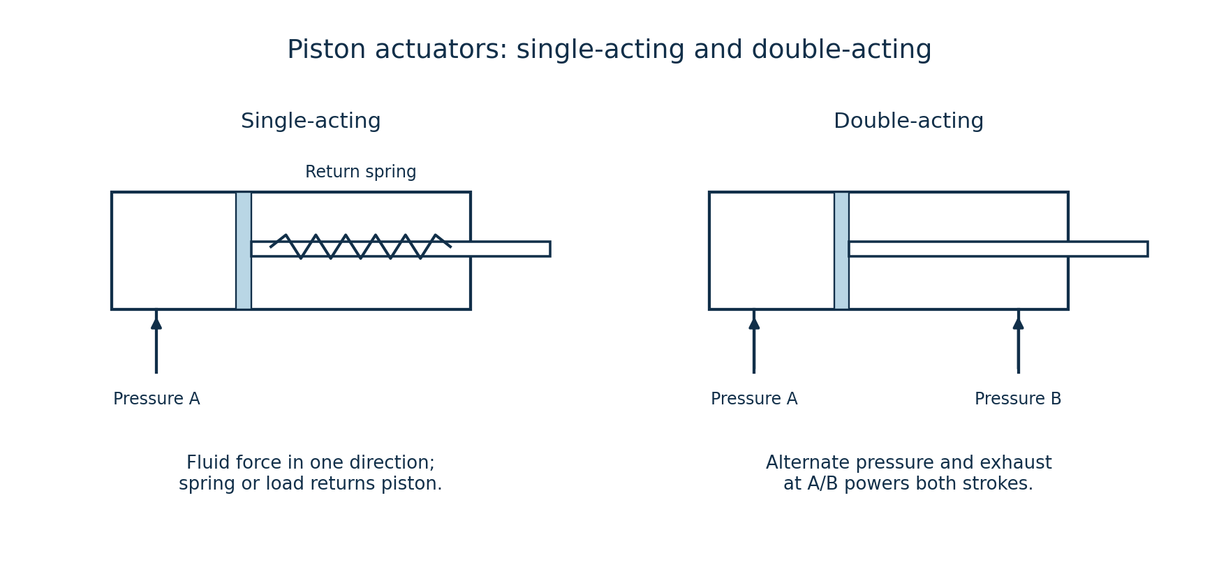
| Single-acting | Double-acting |
|---|---|
| Fluid pressure powers one stroke through one working port; a spring or external load provides the return. | Fluid pressure acts alternately on each side of the piston through two working ports, powering both directions. |
| The unused side is vented as appropriate; control must release fluid from the working chamber for return. | A directional valve supplies one chamber while connecting the opposite chamber to return/exhaust. |
| Typical use: spring-return clamps or simple ejectors. | Typical use: powered feed slides or mechanisms needing force in both directions. |
Question 6(a)
State three areas of application of supervisory control and data acquisition (SCADA) systems.
(3 marks)
Answer
- Water treatment, pumping stations and distribution networks.
- Electrical generation, substations and power-distribution monitoring.
- Oil/gas pipelines or widely distributed industrial process plants.
Question 6(b)
Differentiate between data logging and data archiving as used in SCADA systems.
(2 marks)
Answer
Data logging acquires and records time-stamped measurements, status changes, alarms or events as they occur or at selected intervals. Data archiving retains and organises historical records for longer-term retrieval, trend review and analysis, often using storage policies, compression and backups.
Question 6(c)
Describe each of the following components of a SCADA system: (i) communication network; (ii) human machine interface; (iii) remote terminal unit.
(6 marks)
Answer
| Component | Description |
|---|---|
| Communication network | The wired/wireless links and protocols carrying measurements, status, alarms and supervisory commands between field stations and central systems. |
| Human machine interface (HMI) | The operator’s graphical/text interface for viewing process conditions, trends and alarms and entering authorised set-points or commands. |
| Remote terminal unit (RTU) | A field device that acquires sensor inputs, controls local outputs, performs configured local logic/data buffering and communicates with the SCADA master. |
Question 6(d)
A d.c motor control consists of a programmable logic controller (PLC), start push-button, stop push-button and a lamp indicator which is ON whenever the motor is running. (i) Draw a PLC ladder diagram for the motor control; (ii) Write the PLC program listing.
(9 marks)
Answer
Assign X0 = normally-open START input (1 when pressed); X1 = STOP_OK from a physical normally-closed stop circuit (1 when released/healthy, 0 when pressed or its circuit opens); M0 = RUN memory bit; Y0 = motor-drive/contactor command; Y1 = run lamp. Initialise RUN off. This is a conceptual examination control program; the PLC output drives a suitable motor interface, not the motor power directly.
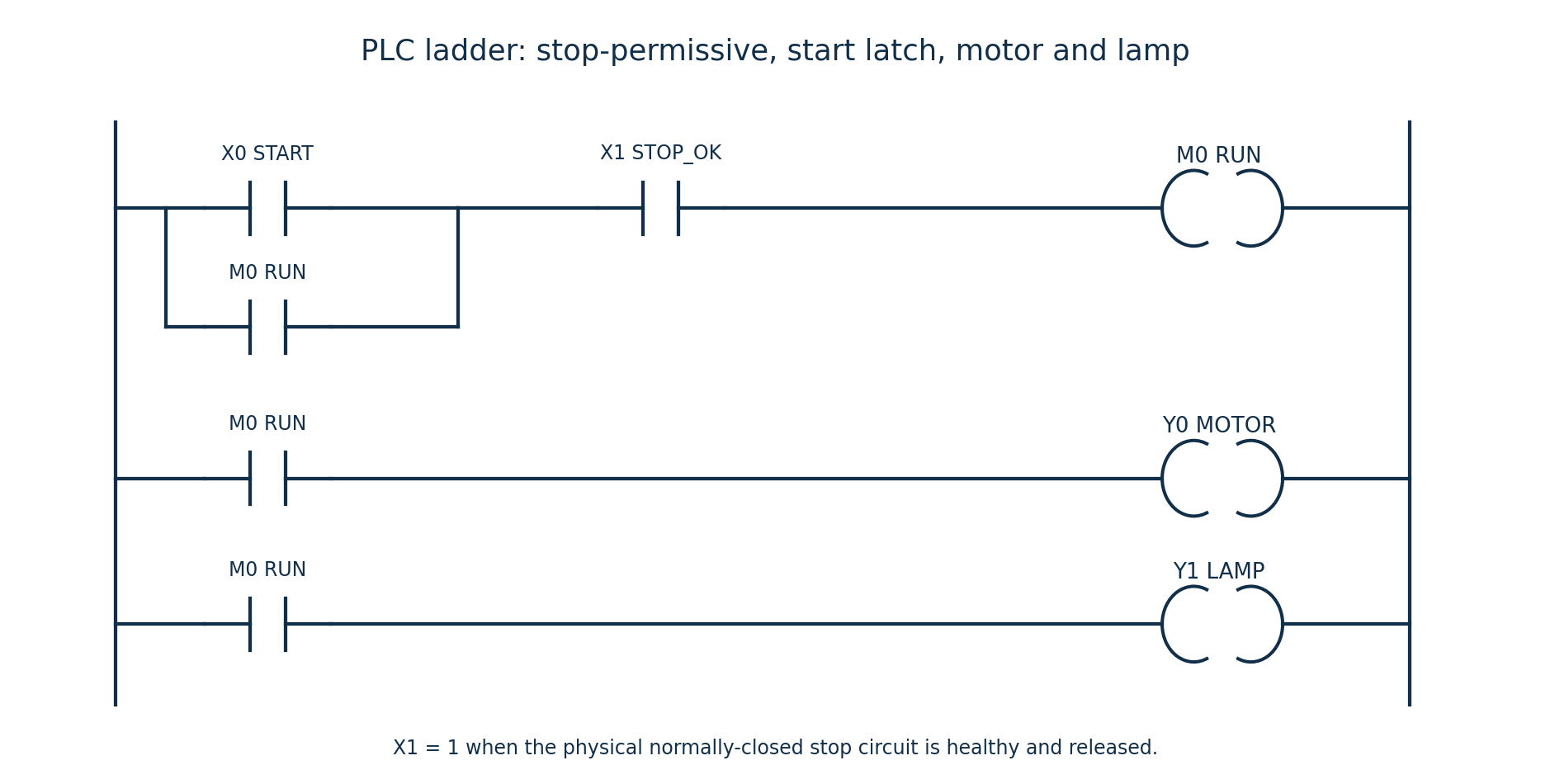
LD   X0       ; START
OR   M0       ; seal-in / hold
AND  X1       ; STOP_OK must remain true
OUT  M0       ; RUN state
LD   M0
OUT  Y0       ; MOTOR command
LD   M0
OUT  Y1       ; RUN lamp
END
The listing uses generic mnemonic instructions; adapt the syntax to the chosen PLC. Its logical update is RUNnew = STOP_OK AND (START OR RUNold); MOTOR = RUNnew; LAMP = RUNnew. X1 is drawn as a logical normally-open contact because it tests the healthy-stop input value; this does not change the physical stop switch from normally closed.
| Scan/event | Motor | Lamp |
|---|---|---|
| idle | 0 | 0 |
| start | 1 | 1 |
| hold | 1 | 1 |
| stop | 0 | 0 |
| release stop | 0 | 0 |
| start and stop | 0 | 0 |
A momentary start energises and holds RUN; pressing stop clears it and both outputs. With only the listed devices, the lamp indicates the motor command. To prove actual rotation, a run-feedback device would be needed; none is supplied in the question.
Question 7(a)
State three causes of mechanical errors in industrial robots.
(3 marks)
Answer
- Backlash or clearance in gears, joints and transmissions.
- Elastic deflection/compliance of links and joints under load.
- Wear, friction or stiction in bearings and drive mechanisms, causing lost or inconsistent motion.
Question 7(b)
(i) Distinguish between control resolution and spatial resolution as used in robotics. (ii) A robot joint has one meter range of movement and a control memory of 8-bit storage capacity. The mechanical inaccuracies are negligible. Determine the: (I) control resolution; (II) accuracy.
(7 marks)
Answer
(i) Control resolution is the smallest change in commanded position distinguishable by the digital controller. Spatial resolution is the smallest distinguishable or achievable physical position increment, including the effects of control quantisation and mechanical limitations. They are approximately equal only when mechanical effects are negligible.
| Step | Working |
|---|---|
| Number of digital states | N = 2⁸ = 256. |
| (I) Nominal control resolution | Using the usual quantisation-bin convention, Δx = range/N = 1/256 m = 0.00390625 m = 3.90625 mm. |
| (II) Quantisation-limited position error | With nearest-position rounding and negligible mechanical errors, maximum rounding error is ±Δx/2 = ±0.001953125 m = ±1.953125 mm. |
| Meaning of “accuracy” here | The half-step value is the assumed quantisation limit, not a general calibration or absolute-accuracy guarantee. |
| Endpoint convention | If all 256 positions include both ends of an exact 1 m span, there are 255 intervals: spacing = 1/255 m = 3.92157 mm and half-spacing = 1.96078 mm. State which convention is used. |
Question 7(c)
Explain each of the following terms as used in industrial robots: (i) work envelope; (ii) load carrying capacity; (iii) speed of movement.
(6 marks)
Answer
| Term | Explanation |
|---|---|
| Work envelope | The three-dimensional region that the robot’s tool reference point can reach within its permitted joint travel and geometry; usable reach also depends on orientation and obstacles. |
| Load carrying capacity | The rated payload the robot may carry under specified reach, motion and load-moment conditions, including the tool and workpiece as defined by the manufacturer. |
| Speed of movement | The rate at which a joint angle or tool position changes, expressed for example in degrees/s for a rotary joint or m/s for tool motion under stated conditions. |
Question 7(d)
Differentiate between each of the following robotic sensors: (i) range sensor and proximity sensor; (ii) position sensor and velocity sensor.
(4 marks)
Answer
| Pair | First sensor | Second sensor |
|---|---|---|
| (i) | A range sensor measures the distance to a target over its measuring range, for example ultrasonic time-of-flight ranging. | A proximity sensor mainly detects whether a target is within a specified nearby zone, for example an inductive metal-presence switch. |
| (ii) | A position sensor measures location or angular displacement, for example a potentiometer or encoder. | A velocity sensor measures rate of linear or angular motion, for example a tachogenerator; velocity may also be derived from position over time. |
Question 8(a)
(i) Explain the term microcontroller. (ii) State two criteria for choosing a microcontroller for a given application.
(4 marks)
Answer
(i) A microcontroller is an integrated circuit containing a processor, program/data memory and input/output/peripheral functions for embedded control.
- (ii) Adequate processing performance and memory capacity for the program and its timing requirements.
- The required number/type of I/O pins and peripherals, such as timers, ADCs or communication interfaces, within the application’s electrical and cost constraints.
Question 8(b)
Differentiate between timers and counters as used in microcontrollers.
(2 marks)
Answer
A timer increments from an internal clock-derived signal to measure time intervals or generate delays/periodic events. A counter increments from external input events/pulses to count occurrences. A timer/counter peripheral can often select either mode; the source of increment pulses is the key distinction.
Question 8(c)
Explain the function of each of the following elements of a microcontroller: (i) central processing unit; (ii) input/output port; (iii) read only memory.
(6 marks)
Answer
| Element | Function |
|---|---|
| CPU | Fetches, decodes and executes program instructions, performs arithmetic/logic and coordinates data transfers and peripheral activity. |
| Input/output port | Provides digital connections between internal registers and external devices, reading input states and driving configured output states through its port circuitry. |
| Read-only/program memory | Stores the program instructions and constant data non-volatilely. The original 8051 uses mask ROM; programmable 8051 derivatives may use EPROM or Flash instead. |
Question 8(d)
Draw a labelled block diagram of the internal architecture of Intel 8051 microcontroller.
(8 marks)
Answer
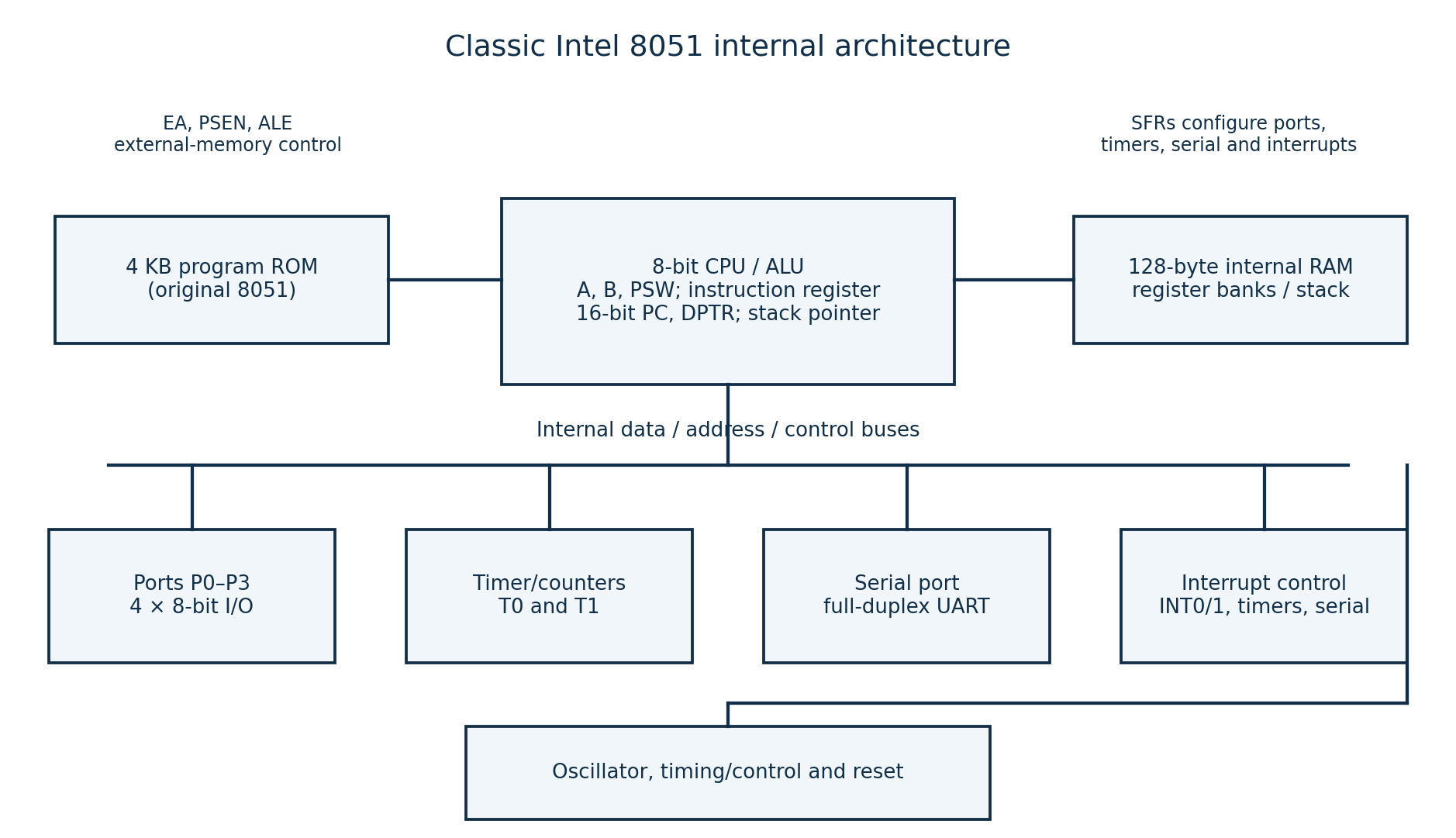
| Block | Key labels |
|---|---|
| CPU and registers | 8-bit ALU, accumulator A, B register, PSW, instruction register/decoder; 16-bit program counter and DPTR; stack pointer. |
| Memories | Original 8051: 4 KB on-chip program ROM and 128 bytes internal RAM, including register banks/stack space; SFRs control the peripherals. |
| Parallel I/O | Four 8-bit ports P0, P1, P2, P3, giving 32 I/O lines. P0/P2 also serve external-memory address/data functions. |
| Timing and communications | Two timer/counters T0 and T1; full-duplex serial port/UART; interrupt-control logic. |
| System control | Oscillator/clock, reset, timing and control, internal buses and external-memory control signals EA, ALE and PSEN. |
The drawing represents the classic Intel 8051 requested by the paper. Enhanced 8051-family devices can add memory, timers, data pointers or other peripherals. The supplied instruction-set/opcode appendices are reference material, not additional questions.