Power Production Systems — October/November 2022
KNEC Diploma in Mechanical Engineering — Module III, Plant option. Printed paper code: 2502/305. Independent revision answers, not an official KNEC marking scheme.
The supplied scan contains printed pages 2–4 and all seven main questions; its cover/instructions page is absent. All supplied questions are answered below. Printed wording is retained, with mathematical typography normalised for readability. Handwritten annotations are not part of the printed questions. Do not infer the missing examination instructions from another sitting.
Question 1(a)
Outline the procedure of carrying out hydrostatic test in a boiler.
(4 marks)
Answer
- Take the boiler out of service, cool, depressurise and positively isolate connected steam, feedwater, fuel and electrical supplies under the approved test procedure. Clean and inspect; prepare fittings as specified by the competent inspector.
- Fill completely with suitable water and vent all high points to remove trapped air. Fit calibrated pressure indication and an approved hydraulic test pump; keep people clear of the test zone.
- Raise pressure gradually to the test pressure specified by the applicable boiler code and inspector. Hold for the prescribed period and inspect for leakage, deformation or pressure loss. Do not substitute a general pressure multiplier for the approved specification.
- Release pressure in a controlled way, drain or preserve as required, record findings and rectify defects. Restore all safety devices and connections and complete required checks before return to service.
This is an examination outline for supervised testing, not an instruction to test an operating boiler.
Question 1(b)
With the aid of a diagram, describe the operation of a water tube boiler.
(6 marks)
Answer
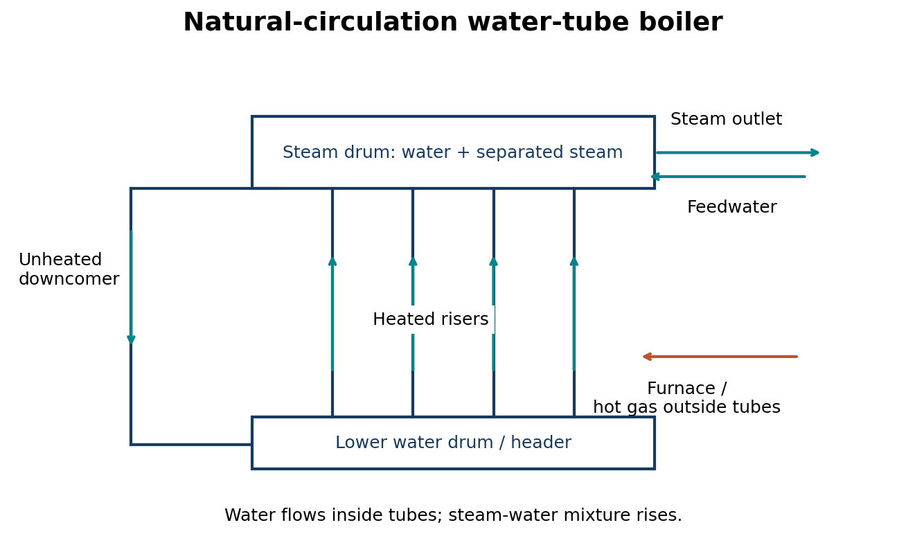
Labelled circulation schematic of a natural-circulation water-tube boiler:
| Position / flow | Component |
|---|---|
| Upper vessel | STEAM DRUM → dry steam outlet |
| Heated path | Lower water drum/header → heated riser tubes ↑ → steam drum |
| Return path | Steam drum → unheated downcomer ↓ → lower drum/header |
| Heat path | Furnace flame/hot combustion gases → outside of riser tubes → flue |
Water flows inside the tubes and hot combustion gases pass outside. Heating produces a lower-density steam–water mixture in the risers, which rises to the steam drum. Steam separates and leaves through the outlet; denser water returns through downcomers, maintaining circulation. Feedwater replaces steam withdrawn. The lower drum/header distributes water and permits collection and controlled removal of sediment.
Question 1(c)
Outline four benefits of an economiser in a boiler.
(4 marks)
Answer
- Recovers otherwise wasted flue-gas heat to preheat feedwater.
- Reduces fuel needed per kilogram of steam.
- Raises overall boiler thermal efficiency and lowers stack heat loss.
- Reduces the temperature difference between incoming feedwater and boiler water, helping reduce thermal shock.
Question 1(d)
With the aid of a diagram, describe a dead weight safety valve used in boilers.
(6 marks)
Answer
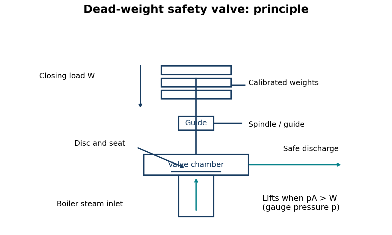
Labelled vertical schematic:
| Position | Part / force |
|---|---|
| Top | Calibrated dead weights ↓ provide closing load |
| Guide | Vertical spindle / guide transmits load to disc |
| Seat | Valve disc rests on seat; steam pressure acts upwards over area A |
| Bottom and side outlet | Boiler steam inlet ↑ → lifted disc → safe discharge outlet |
The valve disc rests on a seat connected to the boiler. A guided spindle and dead weights hold it closed. When the steam force pA exceeds the effective downward load, the disc lifts and discharges steam, limiting pressure. Falling pressure allows the weights to reseat it. Ideally p_set = W/A, using gauge pressure and total effective load. The discharge must remain unobstructed. Heavy weights and sensitivity to motion make this type unsuitable for moving installations; never add weights to raise an authorised setting.
Question 2(a)
Explain the use of the following in a steam plant: (i) condensate lift pump; (ii) hot well.
(2 marks)
Answer
| Component | Use |
|---|---|
| Condensate lift pump | Transfers collected condensate from a low-level receiver/hot well to the feedwater system or higher receiver, overcoming static head and pipe losses. It is not necessarily the high-pressure boiler feed pump. |
| Hot well | Collects condensate leaving the condenser and provides a reservoir for the condensate extraction/feedwater system. |
Question 2(b)
Highlight four advantages of a condenser in a steam plant.
(4 marks)
Answer
- Maintains low exhaust pressure, allowing greater turbine/engine expansion and more useful work.
- Improves cycle thermal efficiency under comparable conditions.
- Recovers condensate for reuse, particularly clean condensate in a surface condenser.
- Reduces make-up water and associated water-treatment costs.
Question 2(c)
With the aid of a diagram, describe the operation of a parallel flow jet condenser.
(5 marks)
Answer
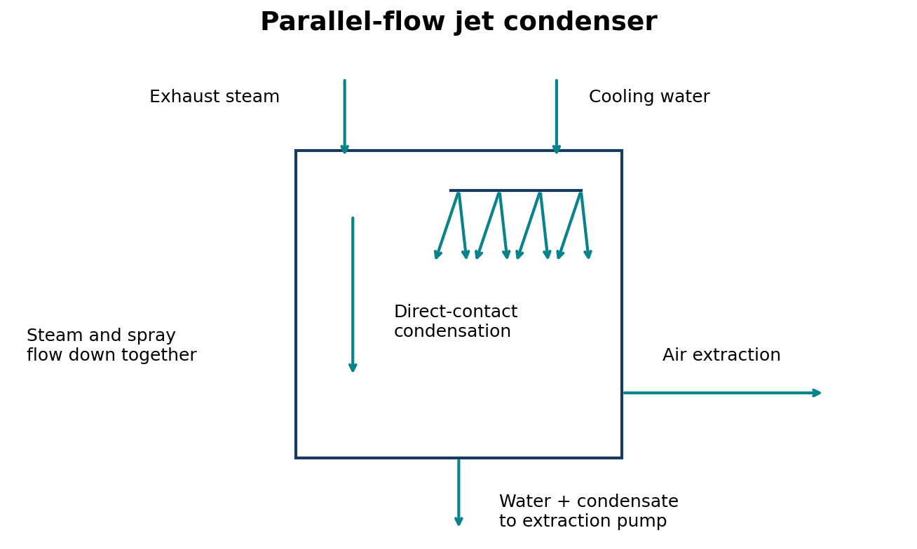
Parallel-flow jet-condenser schematic — both incoming streams move downwards:
| Position | Flow |
|---|---|
| Top | Exhaust steam ↓ + cooling-water sprays ↓ |
| Mixing chamber | Steam and water travel together ↓; direct contact condenses steam |
| Bottom | Mixed cooling water + condensate ↓ → extraction pump / hot well |
| Air extraction | Non-condensable gases → air-extraction connection |
Steam enters and meets cooling water broken into jets/sprays. Both streams flow downwards together. Direct contact transfers latent heat to the water and condenses the steam; volume contraction helps maintain a vacuum. The combined liquid is removed from the bottom and non-condensable gases are extracted. Cooling water mixes with condensate, so reuse as feedwater requires suitable water quality.
Question 2(d)(i)
Define the following terms: (I) dryness fraction; (II) thermal efficiency; (III) equivalent evaporation.
(Question 2(d)(i) and (ii): 9 marks in total)
Answer
| Term | Definition |
|---|---|
| Dryness fraction | For wet steam, x = mass of dry saturated vapour / total mass of vapour–liquid mixture; 0 ≤ x ≤ 1. |
| Thermal efficiency | Useful thermal-energy output divided by energy input. For a boiler, η = m_s(h_s − h_fw)/(m_f × CV). |
| Equivalent evaporation | Mass of water the same useful heat would evaporate from saturated liquid at 100 °C to dry saturated steam at 100 °C (“from and at 100 °C”), often expressed per kilogram of fuel. |
Question 2(d)(ii)
A boiler generates 2500 kg of dry saturated steam per hour at a pressure of 11 bar. The grate area is 4 m² and 110 kg of coal is burnt per m² of grate area per hour. If calorific value of coal is 32180 kJ/kg and the temperature of feed water is 17.5°. Determine: (I) actual evaporation per kg of coal; (II) equivalent evaporation “from and at 100° C”; (III) efficiency of the boiler.
(Question 2(d)(i) and (ii): 9 marks in total)
Answer
Take 11 bar as absolute: the paper does not specify gauge pressure. Use h_g ≈ 2780.7 kJ/kg for dry saturated steam at 11 bar absolute; h_fw ≈ 4.187 × 17.5 = 73.27 kJ/kg; and h_fg at 100 °C ≈ 2257 kJ/kg. The printed feedwater degree sign is interpreted as °C. Small steam-table differences affect rounding.
| Step | Working | Result |
|---|---|---|
| Coal rate | m_f = 4 × 110 | 440 kg/h |
| I. Actual evaporation | m_s/m_f = 2500/440 | 5.682 kg steam/kg coal |
| Enthalpy rise | Δh = 2780.7 − 73.27 | 2707.43 kJ/kg |
| Evaporation factor | 2707.43/2257 | 1.1996 |
| II. Equivalent evaporation per kg coal | (2500/440) × (2707.43/2257) | 6.816 kg/kg coal |
| Equivalent hourly evaporation | 2500 × 2707.43/2257 | 2998.92 kg/h |
| Useful heat per hour | 2500 × 2707.4275 | 6,768,568.75 kJ/h |
| Fuel heat per hour | 440 × 32180 | 14,159,200 kJ/h |
| III. Boiler efficiency | η = 6,768,568.75/14,159,200 × 100 | 47.80% |
If 11 bar means gauge pressure, add local atmospheric pressure and use the corresponding saturation enthalpy. Do not silently mix gauge and absolute steam-table pressures. The printed 9 marks cover both definitions and numerical work; no separate split is shown.
Question 3(a)
(i) Outline three classifications of fuel stating two advantages for each. (ii) Highlight four functions of fuel burners.
(8 marks)
Answer
| Fuel class | Two advantages |
|---|---|
| Solid | Often economical when locally available; storage without pressure vessels. |
| Liquid | Can be pumped/metered for load control; high energy per unit storage volume. |
| Gaseous | Mixes readily with air for controlled combustion; generally little ash handling, depending on composition. |
- Introduce and meter fuel into the combustion space.
- Prepare fuel, including atomisation of liquid fuel where applicable.
- Mix fuel with combustion air.
- Establish and stabilise a suitable flame for controlled heat release and transfer.
Question 3(b)
(i) State six service requirements of a mechanical stoker. (ii) List six maintenance checks carried out on an oil burning equipment.
(6 marks)
Answer
(i) Mechanical stoker:
- Continuous, controllable feed matched to load.
- Even fuel distribution and suitable bed thickness.
- Adequate, well-distributed combustion air.
- Ability to handle the specified fuel size/quality.
- Effective ash/clinker removal and low unburnt-fuel loss.
- Reliable construction with accessible, lubricated and maintainable moving parts.
(ii) Oil-burning equipment:
- Check tanks, pipes, joints and valves for leakage/damage.
- Check filters/strainers for restriction and contamination.
- Check pump condition, oil pressure and specified preheat temperature.
- Inspect atomiser/nozzle and spray for fouling/wear.
- Inspect fan, air passages, dampers and drive.
- Check ignition, flame detection, shut-off and interlocks using the manufacturer’s authorised test procedure.
Question 3(c)
With the aid of diagrams, explain the operation of a four-stroke cycle petrol engine.
(6 marks)
Answer
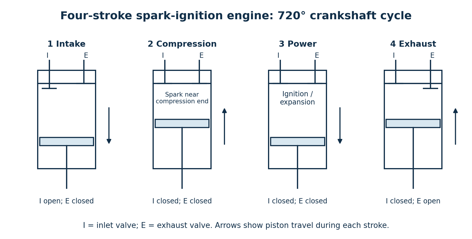
| Stroke | Piston and valves | Operation |
|---|---|---|
| Intake | TDC → BDC; inlet open, exhaust closed | Fresh air–fuel charge admitted in a conventional premixed petrol engine. |
| Compression | BDC → TDC; both valves closed | Charge compressed; spark ignition near end of compression. |
| Power | TDC → BDC; both valves closed for most of stroke | Combustion raises pressure and drives piston down, producing work. |
| Exhaust | BDC → TDC; exhaust open | Burnt gases displaced from cylinder. |
One cycle requires two crankshaft revolutions (720°). Real valve timing includes advance, retard and possible overlap.
Question 4(a)
(i) Describe the following elements of a nuclear power plant: (I) nuclear reactor; (II) heat exchanger. (ii) Outline three types of a nuclear reactor.
(5 marks)
Answer
| Element | Description |
|---|---|
| Nuclear reactor | Contains fuel and the controlled chain-fission reaction releasing heat. Coolant removes heat; control rods regulate neutron population; shielding and containment form protective barriers. |
| Heat exchanger | Transfers heat between separate streams without normal mixing. A PWR steam generator transfers primary-coolant heat to secondary water to make steam. |
Three examples: pressurised-water reactor (PWR), boiling-water reactor (BWR), pressurised heavy-water reactor (PHWR). A BWR makes steam in the reactor vessel rather than in a separate PWR-style steam generator.
Question 4(b)
With the aid of a diagram, describe the operation of a nuclear power plant.
(7 marks)
Answer
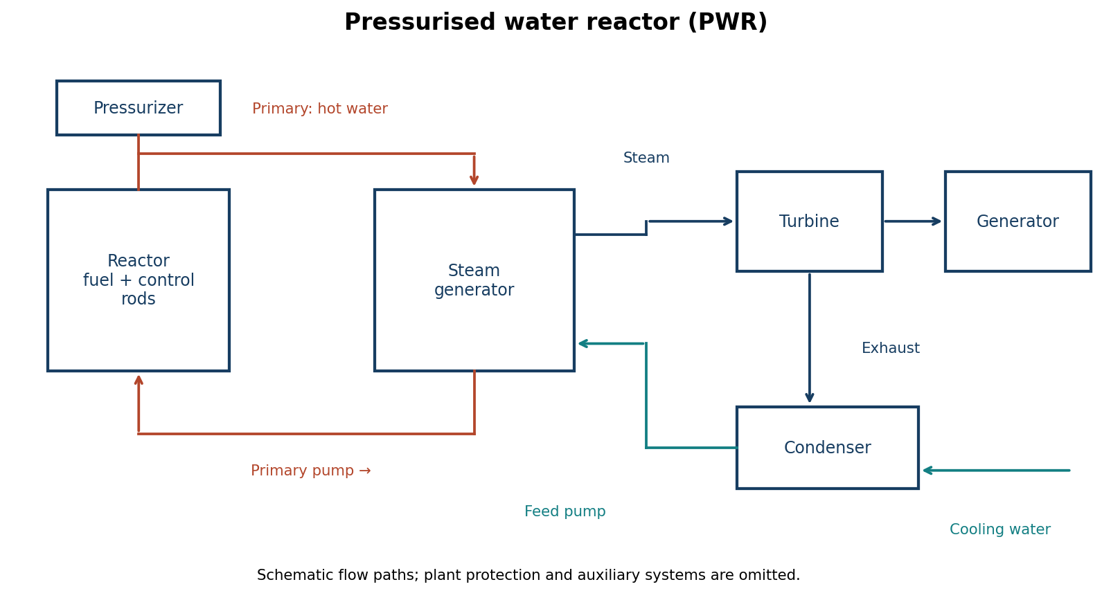
- Controlled fission releases heat into primary coolant in the reactor core.
- The primary pump circulates pressurised coolant through reactor and steam-generator tubes; pressure prevents bulk primary boiling.
- Heat crosses tube walls into secondary water, generating steam without normal mixing of primary and secondary water.
- Steam expands through a turbine coupled to a generator.
- A condenser rejects remaining heat to cooling water and condenses turbine exhaust.
- Condensate/feed pumps return secondary water to the steam generator.
- Control rods, reactor controls, cooling and engineered protection systems maintain required conditions.
Question 4(c)
With the aid of a diagram, describe the circuits of a steam power plant.
(8 marks)
Answer
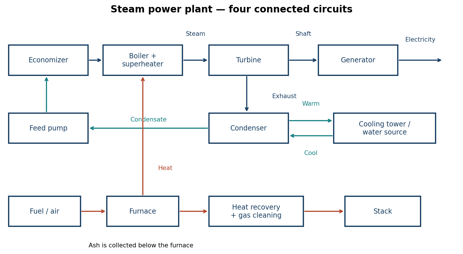
| Circuit | Flow and purpose |
|---|---|
| Coal and ash | Storage → preparation/feed → furnace; ash → collection/disposal. Supplies fuel and removes combustion residue. |
| Air and flue gas | Atmosphere → fan/air heater → furnace → boiler surfaces/economiser → dust collector → chimney. Supplies oxygen and removes combustion products while recovering heat. |
| Feedwater and steam | Condenser/hot well → condensate/feed pumps and heaters → economiser → boiler → superheater if fitted → turbine → condenser. Carries the working fluid round the cycle. |
| Cooling water | Cooling source/tower → pump → condenser → return to source/tower. Removes rejected heat; a surface condenser keeps it separate from condensate. |
Question 5(a)
Outline three types of steam plants.
(3 marks)
Answer
Using exhaust/use arrangement as one consistent classification:
- Condensing plant: exhaust is condensed at low pressure for power generation.
- Back-pressure/non-condensing plant: exhaust leaves at a useful process-heating pressure.
- Extraction-condensing plant: some steam is extracted for heating while the rest expands to a condenser.
The question does not specify a classification basis.
Question 5(b)
(i) State three sources of air into a steam condenser. (ii) Highlight three effects of air leakage into a steam condenser.
(6 marks)
Answer
| Three sources | Three effects |
|---|---|
| Leakage through joints, seals, glands and valve stems operating below atmospheric pressure. | Raises total pressure and reduces vacuum, reducing turbine work. |
| Air dissolved in feedwater/condensate and released in the cycle. | Creates an insulating gas layer at heat-transfer surfaces, impairing condensation. |
| Non-condensables carried with exhaust steam or released from incoming cooling water in direct-contact condensers. | Increases extraction duty; oxygen and other gases can contribute to corrosion. |
Question 5(c)
With the aid of a diagram, describe the operation of an air extraction pump.
(6 marks)
Answer
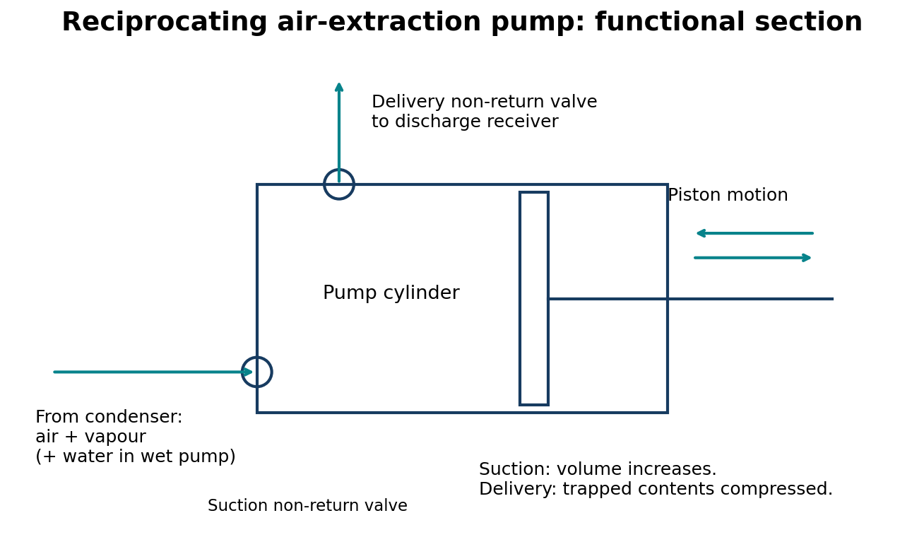
Functional schematic of a reciprocating wet-air extraction pump:
| Component | Flow / motion |
|---|---|
| Condenser connection | Air + vapour → suction non-return valve → cylinder |
| Moving member | Reciprocating piston/bucket ←→ changes cylinder volume |
| Delivery | Cylinder → delivery non-return valve → discharge receiver |
| Wet-air arrangement | Condensate may be extracted with air and residual vapour |
On the suction stroke, increasing cylinder volume lowers pressure below condenser pressure and opens the suction valve, admitting air and residual vapour (and water in a wet pump). On the return stroke the suction valve closes and the contents are compressed until delivery pressure opens the delivery valve. Contents discharge to a receiver; non-return valves prevent backflow. Repeated extraction prevents non-condensable accumulation and maintains vacuum. Liquid-ring pumps and steam-jet ejectors are other arrangements; this schematic describes a reciprocating type.
Question 5(d)
List five maintenance checks and five maintenance tasks of an electrostatic precipitator.
(5 marks)
Answer
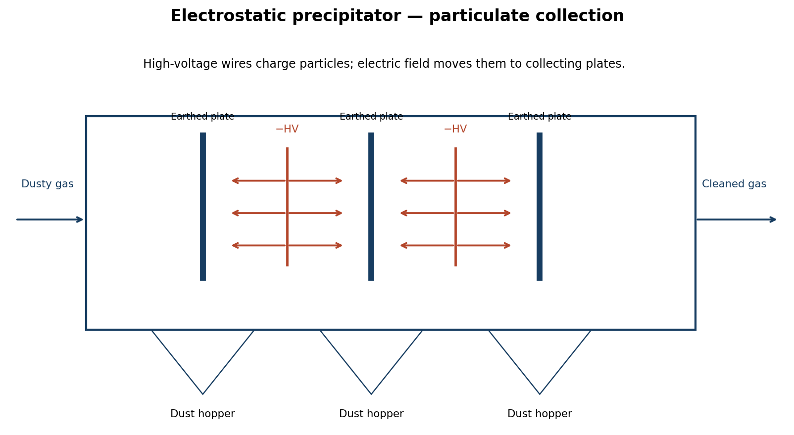
| Five checks | Five tasks |
|---|---|
| Voltage/current trends and abnormal sparking. | Clean/repair contaminated or damaged insulators. |
| Electrode alignment and broken wires. | Realign/replace damaged electrodes and collection components. |
| Insulator cracks, tracking and contamination. | Service rapper mechanisms, drives and specified lubrication. |
| Rapper and hopper-discharge operation. | Clear hopper/discharge obstructions under approved isolation. |
| Casing leakage/corrosion, hopper levels and outlet dust indication. | Repair seals/corrosion and service electrical/protective equipment through qualified personnel. |
Internal maintenance requires shutdown, electrical isolation, verification of absence of voltage, discharge/earthing of stored energy and the site access procedure.
Question 6(a)
(i) List six requirements of a steam distribution system. (ii) With the aid of a diagram, describe a baffle type steam separator.
(8 marks)
Answer
- Deliver the required mass flow at specified pressure.
- Provide sufficiently dry steam of suitable quality.
- Size pipes to limit pressure drop and excessive velocity.
- Minimise heat loss with effective insulation.
- Drain condensate/remove air reliably, avoiding water hammer.
- Accommodate expansion, provide supports and permit safe isolation/access.
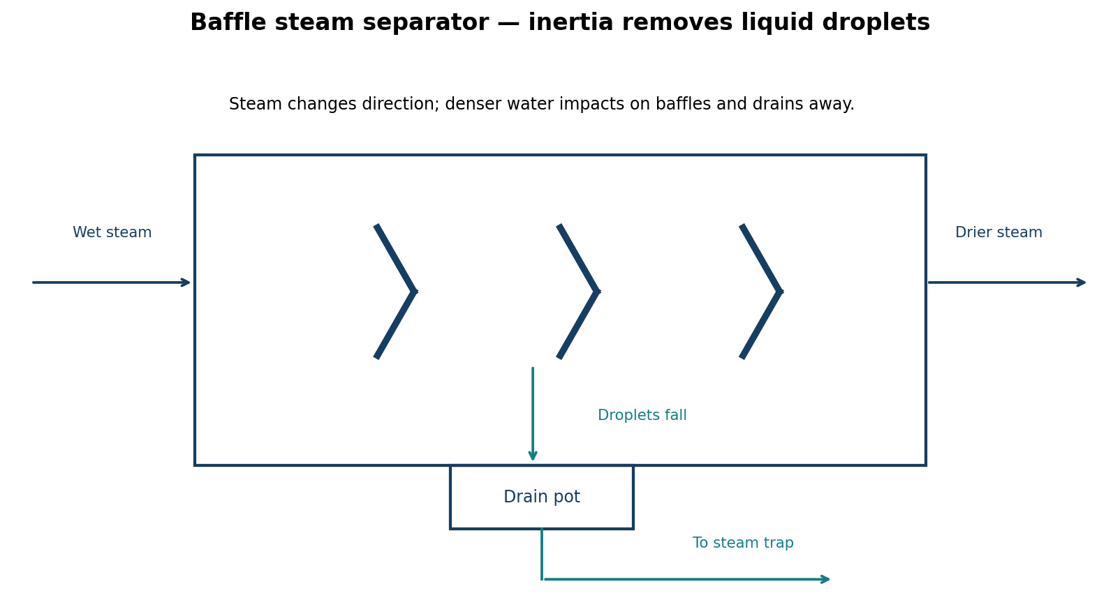
Wet steam enters a body containing baffles. Steam changes direction; higher-inertia droplets hit the baffles and coalesce. Water drains to the collection space and through a correctly selected steam trap; drier steam passes to the outlet. A separator removes liquid droplets, not water vapour, and does not replace boiler-water treatment.
Question 6(b)
List three causes for each of the following problems in a thermostatic steam trap: (i) not enough steam heat; (ii) condensate won’t drain.
(3 marks)
Answer
| Problem | Three possible causes |
|---|---|
| Not enough steam heat | Trap undersized for condensate load; unsuitable/faulty thermostatic element causes excessive condensate holdback; strainer/outlet restriction waterlogs the heating surface. |
| Condensate won’t drain | Element/valve failed closed; strainer/pipe blocked or isolation valve closed; insufficient pressure differential because back pressure/lift exceeds upstream pressure. |
These are possible causes, not a diagnosis. Check load and operating pressure differential before replacing a trap.
Question 6(c)
(i) Explain the following methods of boiler storage: (I) wet; (II) dry. (ii) Outline the procedure for preparing a boiler for inspection.
(9 marks)
Answer
| Method | Explanation |
|---|---|
| Wet storage | Clean and preserve the water side with correctly treated, oxygen-controlled water and an approved means of excluding air. Monitor chemistry, level and any specified pressure blanket according to the lay-up procedure; consider freezing risk. |
| Dry storage | Drain the cooled, isolated boiler, clean and dry thoroughly, then exclude humid air. Use the specified desiccant/dry-air method, inspect moisture/condition and remove temporary materials before correct recommissioning. |
(ii) Preparation for inspection:
- Arrange scope and access with the competent inspector.
- Shut down, cool in a controlled way and depressurise fully.
- Positively isolate and lock out fuel, electricity, steam, feedwater, blowdown and connected energy sources. Prevent hot-fluid entry.
- Drain when safe, prove zero pressure and open manholes/inspection doors under the approved procedure.
- Clean water and firesides to expose surfaces; remove loose scale/soot and provide lighting/access.
- Ventilate; complete confined-space assessment, atmosphere testing, permit and rescue arrangements before entry. Supply records and prior defect information.
- Keep unavailable for service until defects, reassembly, safety-device restoration and required release checks are complete.
Handwritten annotations in the scan are not adopted as operating instructions.
Question 7(a)
Outline four requirements of a flash steam recovery system.
(4 marks)
Answer
- Sufficiently hot, higher-pressure condensate with enough pressure drop to form useful flash steam.
- Suitable low-pressure demand reasonably matched to flash availability.
- Adequately sized/rated flash vessel, vapour piping and pressure-control/protection arrangement.
- Effective residual-condensate drainage and layout avoiding excessive trap back pressure, flooding and water hammer.
Question 7(b)
With the aid of a diagram, explain the operation of a flash steam vessel.
(5 marks)
Answer
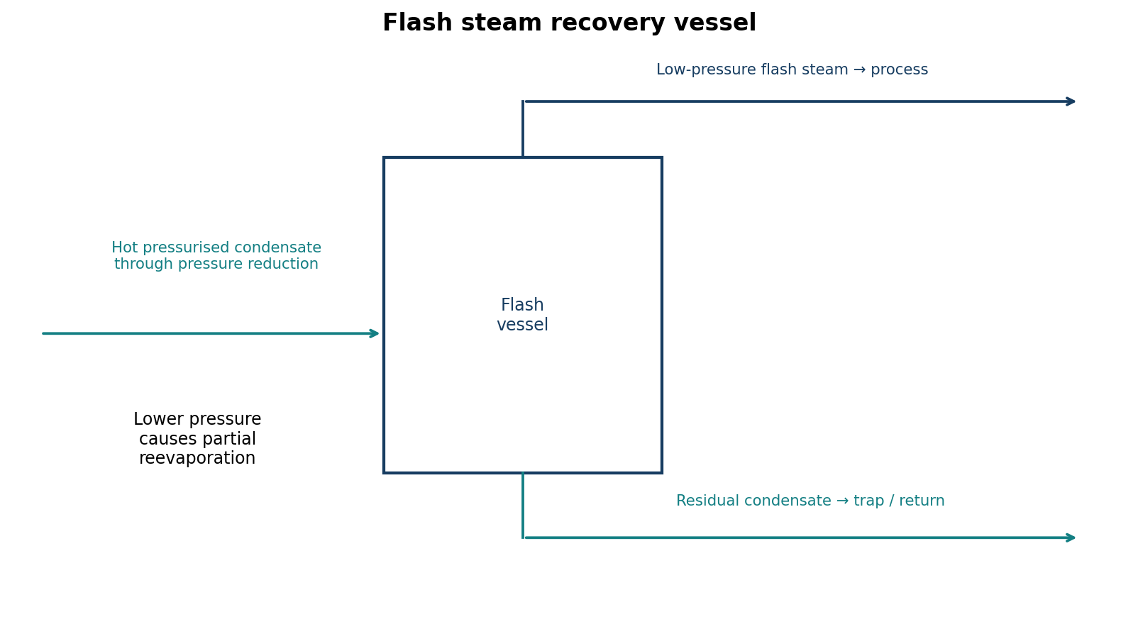
Hot condensate enters a lower-pressure vessel. Inlet enthalpy exceeds that of saturated water at vessel pressure, so part evaporates using its own sensible heat. The larger space reduces velocity and permits vapour/liquid separation. Flash steam leaves at the top for a low-pressure user; residual condensate drains from the bottom through a suitable trap/drainage arrangement. Select pressure control, protection and drainage for the system.
| Ideal energy balance | Meaning |
|---|---|
| x_flash = [h_f(high pressure) − h_f(low pressure)] / h_fg(low pressure) | Fraction of saturated inlet condensate flashed; use actual inlet enthalpy if subcooled. |
Question 7(c)
(i) Highlight four maintenance checks carried out on a steam pipeline. (ii) State two causes and two remedies for each of the following problems in a steam system: (I) water hammer; (II) steam foaming.
(6 marks)
Answer
- Check pipes, joints, valves and flanges for leakage, corrosion and damage.
- Check insulation/weather protection.
- Check supports, anchors, guides and expansion provisions.
- Check drains, traps, strainers and separators for correct drainage.
| Problem | Two causes | Two remedies |
|---|---|---|
| Water hammer | Condensate accumulation due to poor drainage/slope; rapid steam admission to a cold/flooded line drives liquid slugs or causes sudden condensation. | Restore designed drainage, functioning traps and correct slope; drain and warm gradually under the approved start-up procedure. |
| Steam foaming | Excess dissolved/suspended solids; oil/organic contamination stabilising foam. | Control chemistry/TDS through treatment and blowdown; eliminate contamination and clean/treat with specialist guidance. |
Foaming begins at the boiler water surface and can cause carryover. It is not the explanation for every case of wet steam or water hammer.
Question 7(d)
With the aid of a diagram, describe a pelton wheel water turbine.
(5 marks)
Answer

Labelled Pelton turbine flow schematic:
| Part | Flow / function |
|---|---|
| Supply | High-head penstock → nozzle with spear/needle → free jet |
| Jet alignment | Jet tangent to runner pitch circle → bucket splitter (not radially towards shaft) |
| Runner | Double-cup buckets turn jet; shaft takes mechanical power |
| Discharge | Water → spray casing → tailrace near atmospheric pressure |
A Pelton turbine is an impulse turbine for high head and relatively low flow. The nozzle converts pressure head to a high-speed tangential jet. The bucket splitter divides the jet; curved cups turn the streams through a large angle, transferring momentum to runner and shaft. A spear/needle regulates flow, and a deflector may divert the jet during load changes. Water leaves near atmospheric pressure; the casing contains spray rather than acting as a pressure passage.